Veronte Gimbal
General Description
Veronte Gimbal is a high quality device designed to be used in unmanned aerial vehicles.
While using a visible and thermal (optional) cameras, this two axis gimbal provides to any aerial platform high quality sensors essential for any professional task that could require the use of drones.
The gimbal has been designed to be effectively used either in big or small platforms, keeping a light weight and compact size without leaving the enclosure which protects the cameras it embeds.
We have developed four differents variants of Gimbal:
Camera |
Zoom |
HQ Thermal Camera |
|
|---|---|---|---|
Veronte Gimbal: |
HD |
x10 |
Yes, 320x256 resolution |
Veronte Gimbal SC: |
HD |
x10 |
|
Veronte Gimbal Pro: |
Full HD (1080p/60) |
x30 |
Yes, 640x512 resolution |
Veronte Gimbal Pro SC: |
Full HD (1080p/60) |
x30 |
Warning
Veronte Gimbal takes into account airspeed for refrigeration. When used for indoor operation, it will eventually get warm. Consider using an external source of refrigeration for indoor operations longer than 1h.
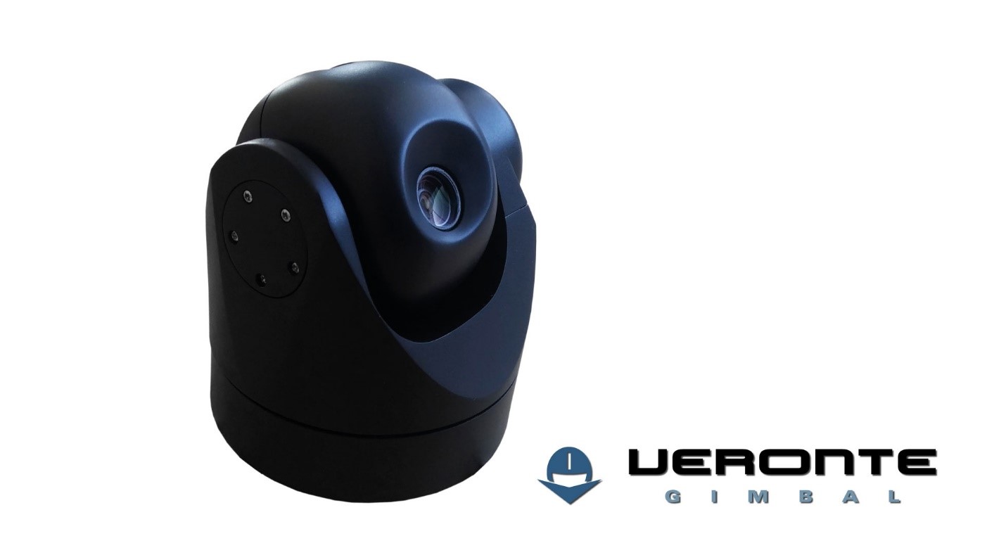
Veronte Gimbalproduct
Dimensions
Height |
Diameter |
Weight |
|
|---|---|---|---|
Veronte Gimbal: |
147mm |
122mm |
820g |
Veronte Gimbal SC: |
136mm |
112mm |
730g |
Veronte Gimbal Pro: |
209mm |
149mm |
1575g |
Veronte Gimbal Pro SC: |
194mm |
149mm |
1485g |
Assembly
Veronte Gimbalshould be attached to the platform using 4x M3 screws, using the threads located on the upper surface.

Veronte Gimbal dimensions
Connections
System connections will be established through a connector LEMO FGG.2B.310.CLAD72Z with 10 pins.
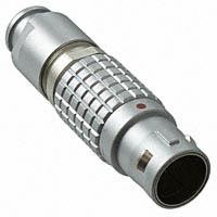
LEMO FGG.2B.310.CLAD72Z connector
Outputs received from the system connector are:
Power 24VDC: Used for video system powering and gimbal electronic controllers. Nominal values are 24V and 0.416 A (10 W).
CAN Bus: It is used to command gimbal’s position, stabilization of the system and for changing different parameters from Veronte Gimbal.
Warning
CAN bus doesn’t have termination resistor, user shall add it based on its own wiring design.
Ethernet: Its utility is based on allowing the user to receive video streaming in real time from both cameras.
Analogic Video: A composite video output which carries camera(s) available signal to the system.
Besides connector Lemo, it will be provided the same connector version but with its panel model connector, with which the different platforms integration may be ease.
The pin-out for the connector is as follows:
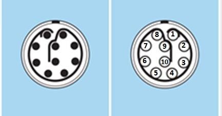
Veronte Gimbal pinout
PIN Nº |
I/O |
|---|---|
1 |
24V |
2 |
GND |
3 |
CANH |
4 |
CANL |
5 |
GND |
6 |
N.C. |
7 |
TD+ |
8 |
TD- |
9 |
RD+ |
10 |
RD- |
Connection Example
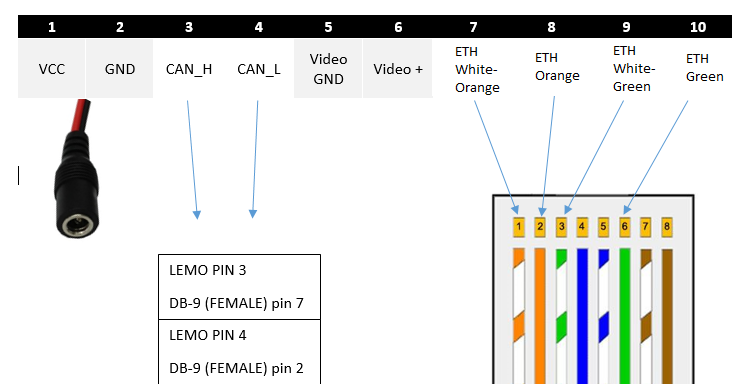
Pinout setup example
Warning
When supplied voltage, Veronte Gimbal will perform an initial check. Please make sure that Gimbal movemente path is clear before powering it up.
Configuration
CAN Messages
Veronte Gimbal is controlled by commanding an angular position by means of a set of CAN messages. Veronte Gimbal also continuously broadcasts information about its state that can be read by any device connected to the CAN bus. The format of the CAN Data messages to communicate with Veronte Gimbal is the following:
CAN Baudrate: 1000000 Bd
Extended ID: No
Endiannes: Little Endian
Command Messages
Messages sent by the controlling device in order to send commands to Veronte Gimbal.
Angle command messages
Format for the messages that the controlling device must send in order to control the position of the Veronte Gimbal:
ID: 1 (Pitch) and 2 (Yaw).
Period: 0.05 s (recommended)
Message:
Nº of Bits
Value
Info
1
0-1
Motor off (0) or Motor on (1)
1
1
Matcher with value 1
32
0-360
Angular position between 0º and 360º
Warning
Veronte Gimbal has a physical limit when moving upwards, which corresponds to 0º Pitch. Correct neutral position for Veronte Gimbal is 0º Yaw - 90º Pitch.
Feedback Messages
Messages sent by Veronte Gimbal through the CAN bus. These messages can be read by Veronte AP and stored into variables:
Encoder feedback
Messages containing the position of the servos read by the encoders.
ID: 34 (Pitch) and 35 (Yaw)
Message:
Nº of Bits
Value
Info
32
0-360
Current encoder position between 0º and 360º
32
0-360
Current commanded position between 0º and 360º
For more information about how to configure CAN messages using Veronte Autopilot please visit: CAN messages
Configuration Example
Below is a step-by-step process on how to configure Veronte Gimbal using Veronte PIPE. This configuration is designed to control Veronte Gimbal using a Virtual Stick on the Veronte Pipe Workspace.
User Variables
We will first rename a set of user variables to use them for storing control values. For information about how to configure user variables visit: User Variables Configuration
Name |
Initial Value |
Purpose |
|---|---|---|
Gimbal Yaw Output |
0 |
Stores the desired position for the Veronte Gimbal Yaw |
Gimbal Pitch Output |
0 |
Stores the desired position for the Veronte Gimbal Pitch |
Stick Configuration
We will be using a Virtual Stick located on the Veronte PIPE Workspace to control the position of Veronte Gimbal. First we will need to check that control through Virtual Sticks is enabled for our configuration. Go to Setup/Devices/Stick/Virtual Stick and check the following values are correct:

Virtual Stick configuration
Then we will create a Virtual Stick Widget on the Workspace and assign the channels we want to control. In this case we will use stick channels 9 and 10:

Virtual Stick channel selection
Finally we need to check that our Virtual Stick is on. In order to do that click on the antenna icon on the top left of the Virtual Stick widget. When the stick is correctly recognized, the Mode indicator on the Veronte pannel will turn green. Value of stick channels can be monitored displaying variables ‘Stick Input’ r9 and r10. Remember to save the Workspace for the new variables to be loaded correctly:

Virtual Stick connection checking
Operations
Now we will create a set of operations that will use the chosen user variables to control the position of Veronte Gimbal. The following operations have to be located on the ‘Continuous execution’ list (Right side). Operations are executed in order from first to last so maintaining the order established below may be important:

Operation creation
First operation will be the one controlling the commanded position for the yaw angle. This will be simply a value provided by the stick. Since the stick range goes from 0 to 1, this value will be multiplied by 360 to get a full 0º-360º range. We will also add a Yaw correction, using the attitude of the platform, to keep the current gimbal yaw even if the aircraft changes its yaw angle. We will use a Linear Expression type operation:
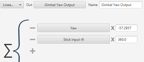
Yaw configuration
The operation for controlling Pitch will be similar, but this time range will be from 70 º (slightly tilted up) to 180º (looking down):
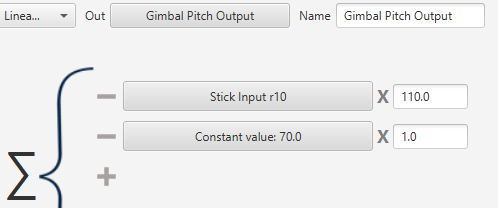
Pitch operation configuration
CAN Messages
Last step is configuration of CAN messages according to 4.1. Below you can find a set of screenshots showing how build the correct messages in Veronte PIPE:
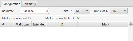
Gimbal configuration menu
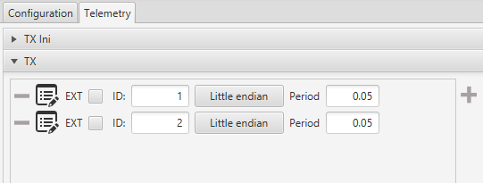
Gimbal telemetry menu
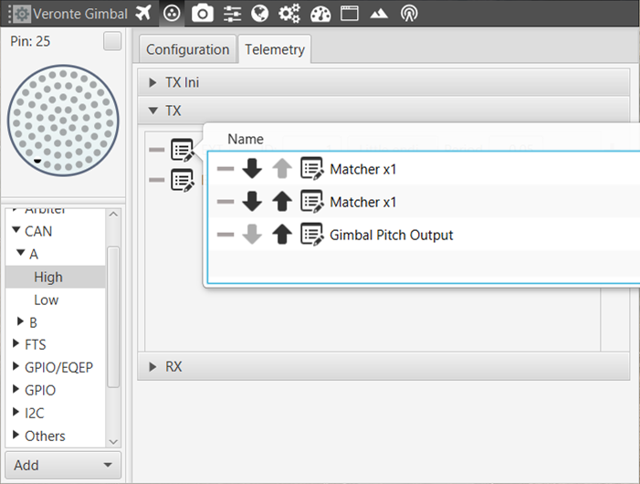
CAN message configuration
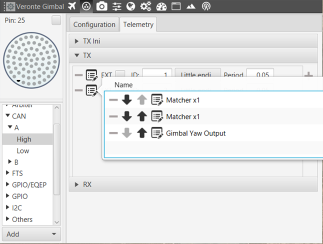
CAN message configuration - 2