Servo Configuration
Once the Autopilot has been installed and connected according to the guidelines that appear in section 2.1 of this manual, the first step of the configuration process is the adjustment and trimming of the servos. This section contains the instructions to follow in order to trim the platform servos using Veronte Pipe.
Quadcopter servos
Servos Output
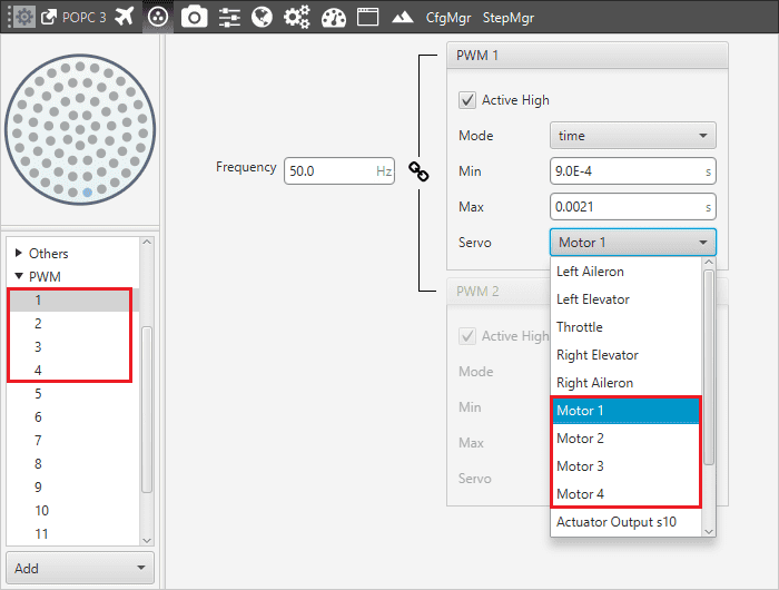
In this case, the controls of the airplane are the four electric motors. Motors can be controlled by changing their thrust (from 0 to 1), so each one of them corresponds to a pin of the connector and they must be positioned in the same order in an S vector who represents the Actuator Output. It is possible to connect any pin to any command but the easiest way to perform it and avoid confusion is by following the pins number.
Quadcopter motors connections
.jpg)
Motors numbers
In this case, it is necessary to use 4 pins:
Motor 1: Actuator Output s7.
Motor 2: Actuator Output s8.
Motor 3: Actuator Output s9.
Motor 4: Actuator Output s10.
SU Matrix
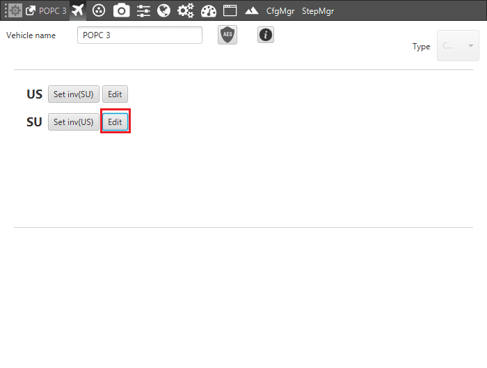
At this point, the S vector is defined and the SU matrix can be edited. By clicking on Edit it is possible to configure the relation between the controller outputs (U vector) and the servo movements (S vector).
SU matrix edit
Warning
This panel shows the reference system of the aircraft too. It must be positioned in the same way of the Autopilot’s one. If it results different, it can be edited by clicking on the corresponding axis in order to reverse its direction.
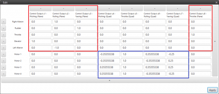
SU Matrix (blue – airplane, red – quadcopter)
The Hybrid during quadcopter phases is configured as follow:
Pitch Angle Control: Control Output 5 is configured to perform a positive pitch angle change when motors 1-4 decrease their RPMs and motors 2-3 increase RPM value.
Thrust Control: the Control Output 6 is the one that allows a thrusting change (0-1).
Roll Angle Control: Control Output 7 is configured to perform a positive roll angle change when motors 1-2 decrease their RPMs and motors 3-4 increase RPM value.
Yaw Angle Control: Control Output 8 is configured to perform a positive yaw angle change when motors 2-4 decrease their RPMs and motors 1-3 increase RPM value, in this case with different proportions.
Plane Servos
Servos Output
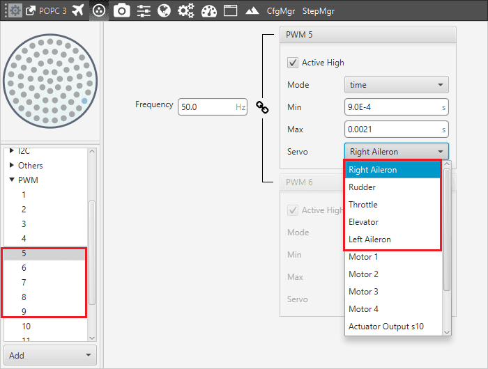
In this case, it is necessary to configure a conventional aircraft configuration, so there are five controls: elevator, two ailerons, rudder and throttle. Each one of these controls is assigned to a value of the Actuator Output vector (s) according to the pin where it is connected and avoiding to use the quadcopter connection pins.
Plane servos connections
Right Aileron: Actuator Output s1
Elevator: Actuator Output s4
Throttle: Actuator Output s3
Rudder: Actuator Output s2
Left Aileron: Actuator Output s5
When the five controls are defined, the SU matrix plane part (blue part) can now be completed. In the case of this Hybrid, each control channel is related with only one servo: the pitching with the elevator, the rolling with the ailerons, the yawing with the rudder and the thrusting with the throttle:
Pitching (u1): Actuator Output s4 (Elevator)
Thrusting (u2): Actuator Output s3 (Throttle)
Rolling (u3): Actuator Output s1 and s5 (Ailerons)
Yawing (u4): Actuator Output s2 (Rudder)
System Trim
As a final step, the system has to be trimmed. This action can be performed by moving servos in three different positions: zero position, minimum and maximum deflection angle (angles are usually limited physically). These positions must be inserted and saved in the software by clicking on “Set” when the actuator is in the desired position.
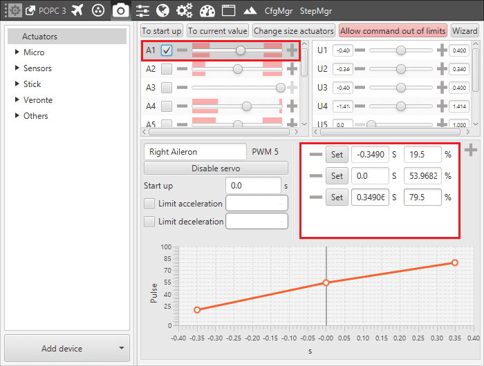
Actuator 1 trimming
The picture shows the setting of the elevator number 1:
Minimum: -0.34906 [rad] deflection ; 19.5%.
Zero position: 0.0[rad] deflection ; 53.9682%.
Maximum: 0.34906 [rad] deflection; 79.5%.
Warning
The actuators can be moved directly from Veronte Pipe only when the system is in an Initial phase. During the actuator run, if the desired position is in the “out of range” zone (red zone), it is possible to click on “Allow command out of limits” in order to move completely the actuator and find the correct position.
This procedure can be performed in the same way by using a “wizard”. This tool allows moving actuators limits easily and finding the correct range.
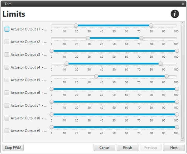
Trim wizard tool
In order to perform a final checking, it is possible to select the desired channel and testing pitch, roll, yaw and thrust controls.
The image below shows a pitching output testing. By moving the U1 control, surfaces must change the position according to the reference system: positive corresponds to nose down and negative to nose up.
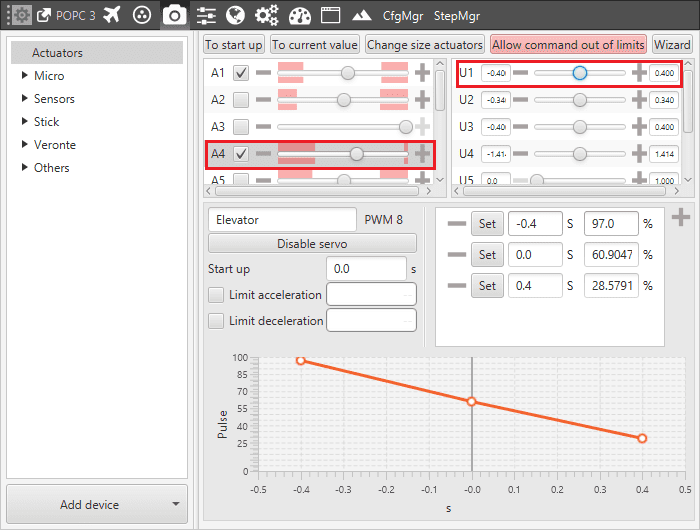
Pitching test
Quadcopter motors connections
Quadcopter motors connections
Quadcopter motors connections