Control Blocks
Control blocks are those related to the creation of control loops:
Control Blocks
PID blocks
PID blocks allow the user to build a PID controller.
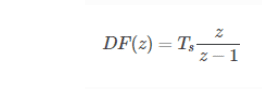
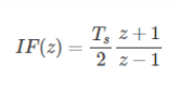
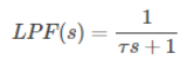
The PID mathematical implementation in Veronte is the following:
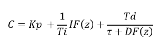
PID Model
Where:
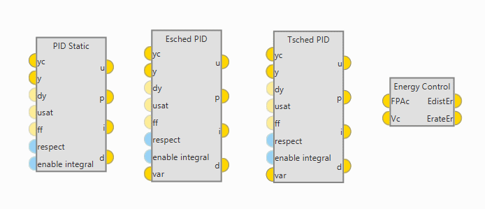
Inputs and outputs
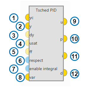
PID Block
yc: Target value, desired state that the controlled variable must acquire.
y: Closed loop feedback, current value for the controlled variable.
dy (optional): Time derivative for feedback. If provided, this value will replace discrete derivative of y in the derivative term calculation.
usat (optional): initial output value. Needed for the ‘respect’ feature.
ff (optional): feedforward value. Offset applied at PID output.
respect (optional): enable/disable the respect feature. Default is configured in the PID menu.
enable integral (optional): enable/disable intergal term. Default is enabled.
var (only scheduling blocks): scaling variable for gain scheduling.
u: pid output
p: proportional term
i: integral term
d: derivative term
Configuration
Double click on a PID block to open its configuration menu
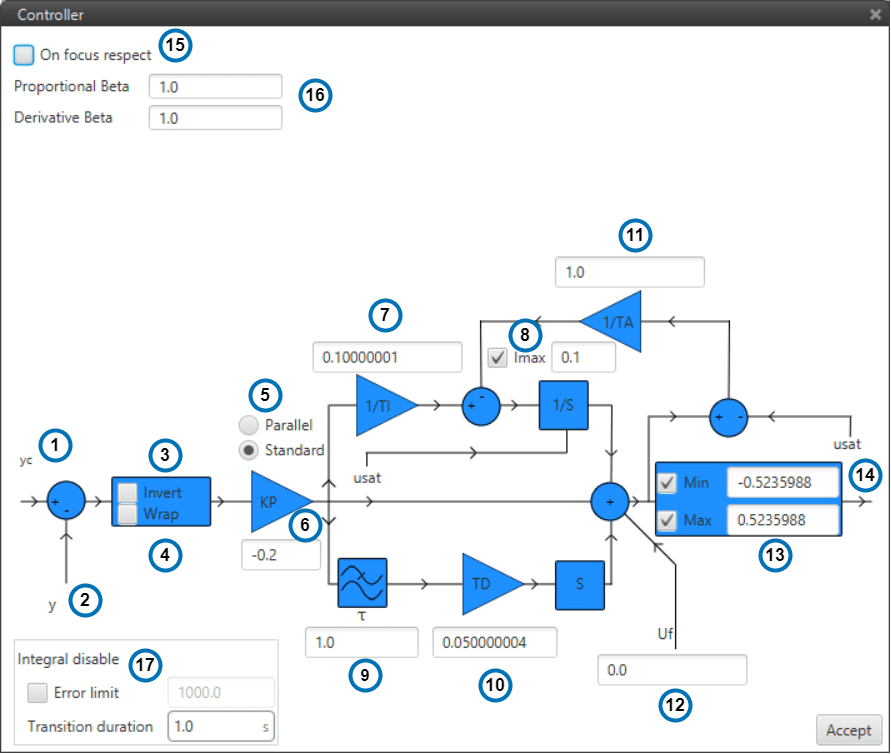
PID Configuration
yc: Input variable.
y: Feedback variable.
invert: Apply a -1 gain .
wrap: Perform a [-pi,pi] wrap.
parallel/standard: In parallel mode, PID gains are independent. In standard mode, I & D gains are scaled by P gain.
KP: Proportional gain.
1/TI: Integral gain.
Imax: Maximum value for integral term. Value must be possitive and the limit applied is symmetrical ([-Imax,Imax]).
tau: Time constant for the derivative term first order LPF.
TD: Derivative gain.
TA: Anti-windup gain. Recommended value around x10 KI. Unloads integral term if output is saturated.
Uf: Output offset. Feedforward value is also applied at this point.
Min/Max: Output limits.
u: PID output.
On focus respect: If respect is enabled, when the PID is first executed, an initial I value will be applied so that ‘u’ = ‘usat’ for the first iteration.
Proportional/Derivative Beta: yc scaling for proportional and derivative terms. Unless necessary, value should always be 1.
Integral disable: disables integral term if (yc - y) > Error limit.
Tip
Remember to always use ‘wrap’ for direction controllers, such as ‘Heading’ or ‘Yaw’ PIDs. This will allow the UAV to always turn in the right direction.
Danger
Applying changes to ANY Program will RESET all PIDs Integral terms. Make sure that this is not dangerous to your operation or make a proper use of the ‘Respect’ feature if you are planning to make in-flight program changes.
Scheduling
Schedulling allows to adapt PID gains and parameters depending on flight conditions:
Proportional Scheduling
ESched block allows to scale KP gain using an external variable. This control block works in Standard mode, so integral and derivative gains are changed in the same proportion.
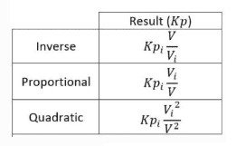
PID Proportional Scheduler
Min and Max values make reference to the Scaling Variable.
If the variable is out of bounds the value of Kp for the closest limit will be applied.
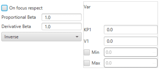
Table Scheduling
TSched block allows to scale most PID parameters using an external variable.
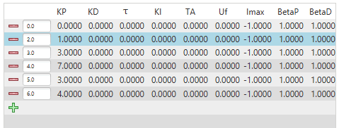
PID Table Scheduler
If the variable is out of bounds the values for the closest point will be applied.
Values between points are linearly interpolated.
Total Energy Control
Total Energy Control is a strategy for the control of Fixed Wing aircrafts.
The aim of this strategy is to decouple speed and altitude controls.
The Total Energy Control block will provide two errors that must be minimized in order toobtain the desired speed and flight path:
Energy Distribution Error: Distribution of sistem energy between kinetical and geopotential energy. This error should be minimized using the Elevator.
Energy Rate Error: Rate of change of the Total System Energy. This error should be minimized using Throttle.
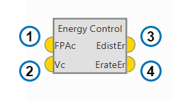
Energy Control Block
FPAc: Desired Flight Path Angle.
Vc: Desired Speed.
EdistEr: Error in the required Energy Distribution.
ErateEr: Error in the required Energy rate.
Some parameters of the Energy algorithm can be modified by Double clicking on the block:
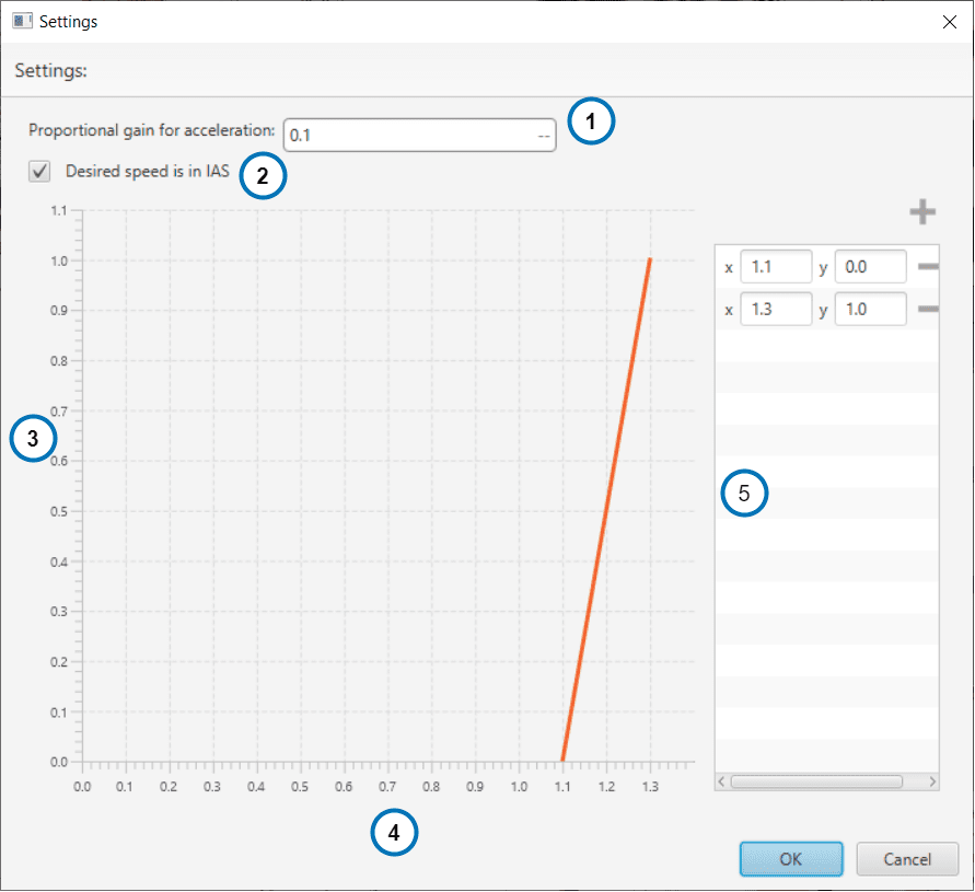
Energy Control Menu
Proportional Gain for Acceleration: in short, its an indication of how aggresive the algorithm is when trying to gain speed. The higher the value, the faster the algorithm will try to ‘dive’ in order to gain speed. A typical recommended value is around 0.1. Higher values are only recommended for fast maneuvering platforms.
IAS/GS:If checked, the block will use variable ‘0 - IAS (Indicated Airspeed)’. If unchecked, variable ‘2 - GS (Ground speed)’ will be used as a reference instead. Use of Ground Speed is not recommended unless Airspeed measurement is not available.
Stall correction coefficient: If 1, energy control is balanced for altitude and speed. If 0 only speed control is taken into account.
Speed/Stall ratio: Ratio between current speed and minimum speed.
Stall correction interpolation function: Define how the relation function between the stall correction coefficient and the Speed/Stall ratio.
Note
The Stall correction coefficient is a Safety tool that can be used to sacrifice altitude control in order to improve speed control when speed gets close to the minimum speed selected in the Envelope