Transmitter
The wired connected transmitters are configured through the following menus.
PPM
This tab provides the options to configure a Pulse Postion Modulation (PPM) radio controller to control the platform fitted with the autopilot.
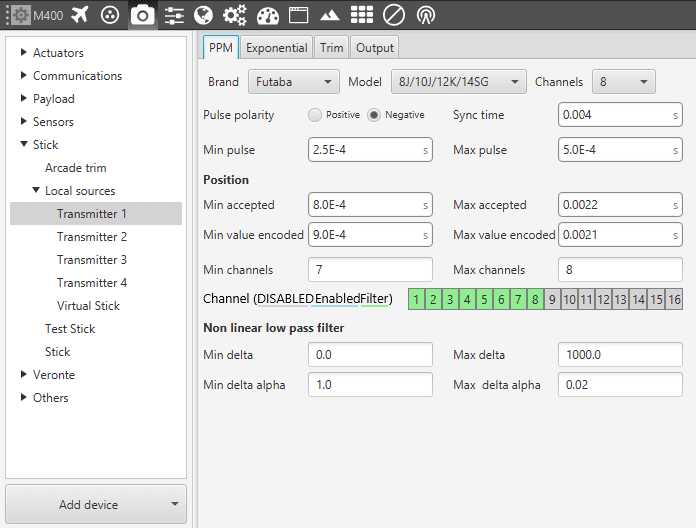
Stick Transmitter - PPM Configuration Parameters
Brand, Model & Channels. Veronte Pipe has been configured to provide the user with the expected parameters to configure different transmitters models:
Futaba.
Model 8J/10J/12K/14SG with 8 channels.
Model 12K/14SG with 12 channels.
Model T18SZ with 8 channels.
Jeti.
DC 16 / DC 24 with 16 channels.
FrSky.
Taranis 9XD with 8 channels.
X12S with 8 channels.
Polarity. Indicates the pulse polarity. The image below shows a positive signal.
Sync time. Minimum time on the PPM output till the next frame. It tells the receiver to reset its channel counter.
Minimum/Maximum pulse. Pulse length, it depends on the system and it is a constant value (usually 0.2-0.5 ms).
Position – Minimum/Maximum accepted. Pulse length accepted for each channel. Standard for R/C servos uses a pulse of 1 ms for the maximum position at one end, 1.5 ms for the midpoint and 2 ms for the maximum position at the opposite end.
Minimum/Maximum encoded. If there is noise and the signal is varying around the minimum/maximum values accepted, Veronte will encode those values to the ones set here. For instance, a pulse length between 0.8-0.9 ms will be considered as one of 0.9 ms.
Channels. Sets the number of channels accepted (minimun and maximun). Besides, it is possible to Disable/Enable/Filter each channel individually.
Non linear low pass filter. Default parameters are recommended.
When some data is out of the established ranges, Veronte will discard that frame to avoid a possible malfunction. The next image clarifies the parameters introduced previously.
Transmitter - PPM Signal
Exponential
The second tab in allows the user to define an exponential stick response for every channel.
Allowed inputs go from 0 to 1 and there is a graph showing the generated response curve, as can be seen in the following figure.
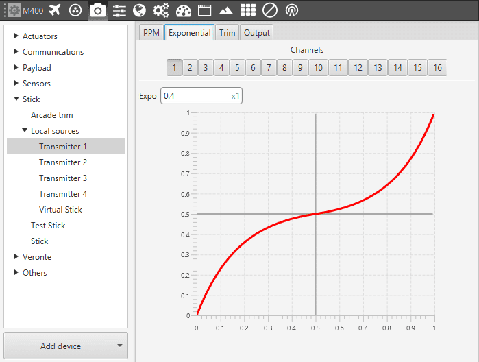
Transmitter - Exponential
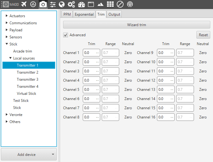
Trim
The third tab available is the Trim option. On the upper part, there is a Wizard trim button. The latter will guide the user through some pop-up windows.
Transmitter - Trim
If that option is not chosen, ththe user can toggle the Advanced option and set the expected trim values manually. The user should have a deep knowledge on its transmitter if this option is selected. Finally, on the right hand side, the Reset button puts every parameter back to 0.
Output
Lastly there is the Output tab. Once the stick has been configured, the commands that arrive at the ground autopilot have to be sent to the air one. Here the user sets the receiving port and process the incoming commands.
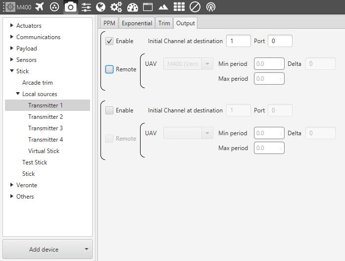
Transmitter - Output
Once enable is flagged, the user indicates to which channel of the air autopilot (AIR) will be sent the first channel received in the ground segment (GND). The channels arrive at the platform in order and without spaces between them i.e, if at the GND channels 1,2,3,4 and 6 are enabled, the AIR will recieve channels 1,2,3,4 and 5. Therefore channel 6 of the stick will be channel 5 in the AIR configuration.
The option remote allows the delivery of the commands to the platform by indicating the address of the UAV. There is also the option Broadcast, where the commands are sent to all the air autopilots linked to the GND).