Model Simulation
This section will allow the user to load a pre-existing model/configuration to the autopilot and perform a mission simulation with the combined help of the software X-Plane. The content is organized in 3 sub-sections: how to load the template into Veronte autopilot, setting XPlane and Veronte Pipe so they can communicate, and how to run a simulation.
Loading a Template to the Autopilot
When the autopilot is connected, in the side panel click on ![]() and then click on Import PDI.
and then click on Import PDI.
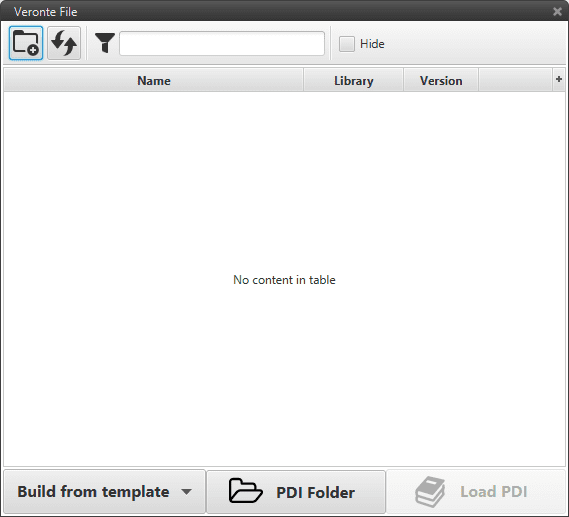
Import a Configuration File
The Import Configuration option displays a window (shown in the previous figure) where the user can select a file to be uploaded. The option of interest for the scope of this section is Build from template. The software is fitted with a set of default configurations (templates) so the user can have reference of what a fixed wing, quadcopter or ground configuration should look like.
There are three other options to select a configuration file. For more information about the logical calibration of the servos check Import Configurations.
The configuration file is loaded in the software (Veronte Pipe), but it is not loaded on the autopilot until the Save button ![]() is pressed.
is pressed.
X-Plane and Veronte Pipe Setup
Integration of Veronte Autopilot within the X-Plane simulator enables the user to perform a Harware-In-the-Loop (HIL) simulation. HIL simulation enables testing an effective model of the vehicle by adding the complexity of the plant under control.
Veronte Pipe
Once a template has been loaded into the autopilot, the HIL simulation parameters need to be set. On the side panel, click on ![]() and then click on HIL. A pop-up window will appear (see the figure below) and it has to be filled in as follows:
and then click on HIL. A pop-up window will appear (see the figure below) and it has to be filled in as follows:
IP |
127.0.0.1 |
Receive Port |
49005 |
Send Port |
49000 |
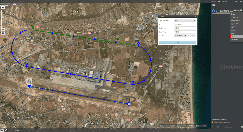
Veronte Pipe – HIL Configuration
X-Plane
X-Plane 10 or 11 are compatible with Veronte Pipe to perform HIL simulations. Here, necessary settings on X-Plane 11 to communicate with Veronte Pipe are detailed. If X-Plane 10 is used, the user can check X-Plane 10 Settings.
On X-Plane’s main menu, go to Settings and then to Data Output. Here, the data tha will be shared with Veronte Pipe is defined:
Variables 3, 4, 16, 17, 18, 20 and 21 should be selected on the column Network via UDP.
UDP rate should be set to its maximum value of 99 packets/sec.
Network configuration should be set to IP Address 127.0.0.1 and Port 49005.
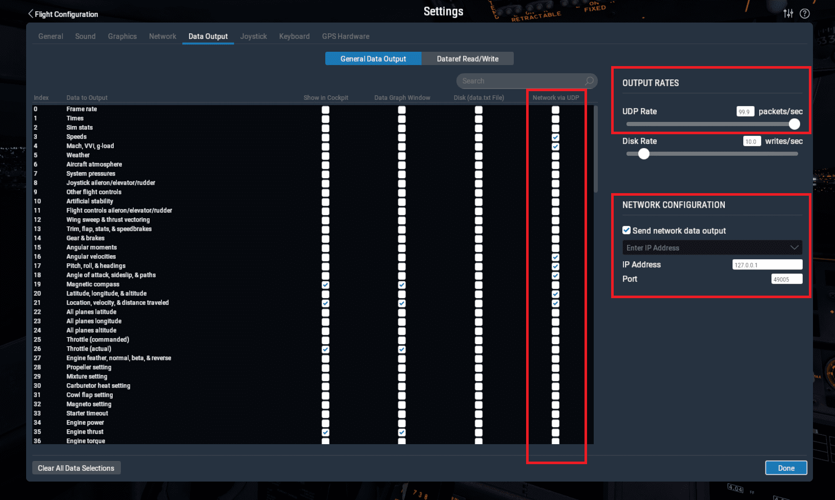
X-Plane 11 I/O configuration
X-Plane 11 provides a tool called Plane Maker where the user can create the platform model. Once the vehicle model has been created, it can be integrated on the X-Plane 11 simulator by following next steps:
Copy the model folder to the Aircraft folder within the X-Plane 11 installation directory.
Copy the content of the Airfoils folder available on the aircraft model folder to the Airfoils directory within the X-Plane 11 installation directory.
Executing a Simulation
Before starting a simulation with one of the built-in templates of Veronte Pipe, the user needs to take into account the following:
The missions defined on this configurations are set at Alicante’s airport (LEAL), with runway 10 as the default one.
The flight envelope and all the flight control settings and transitions are tailored for the template model. Therefore, the user might need to modify some parameters in order to have their own model flying as desired.
Let us supose the user has created a fixed wing model with a V-tail configuration on Plane Maker. Then, the most suitable template on Veronte Pipe would be Fixed Wing V-Tail:
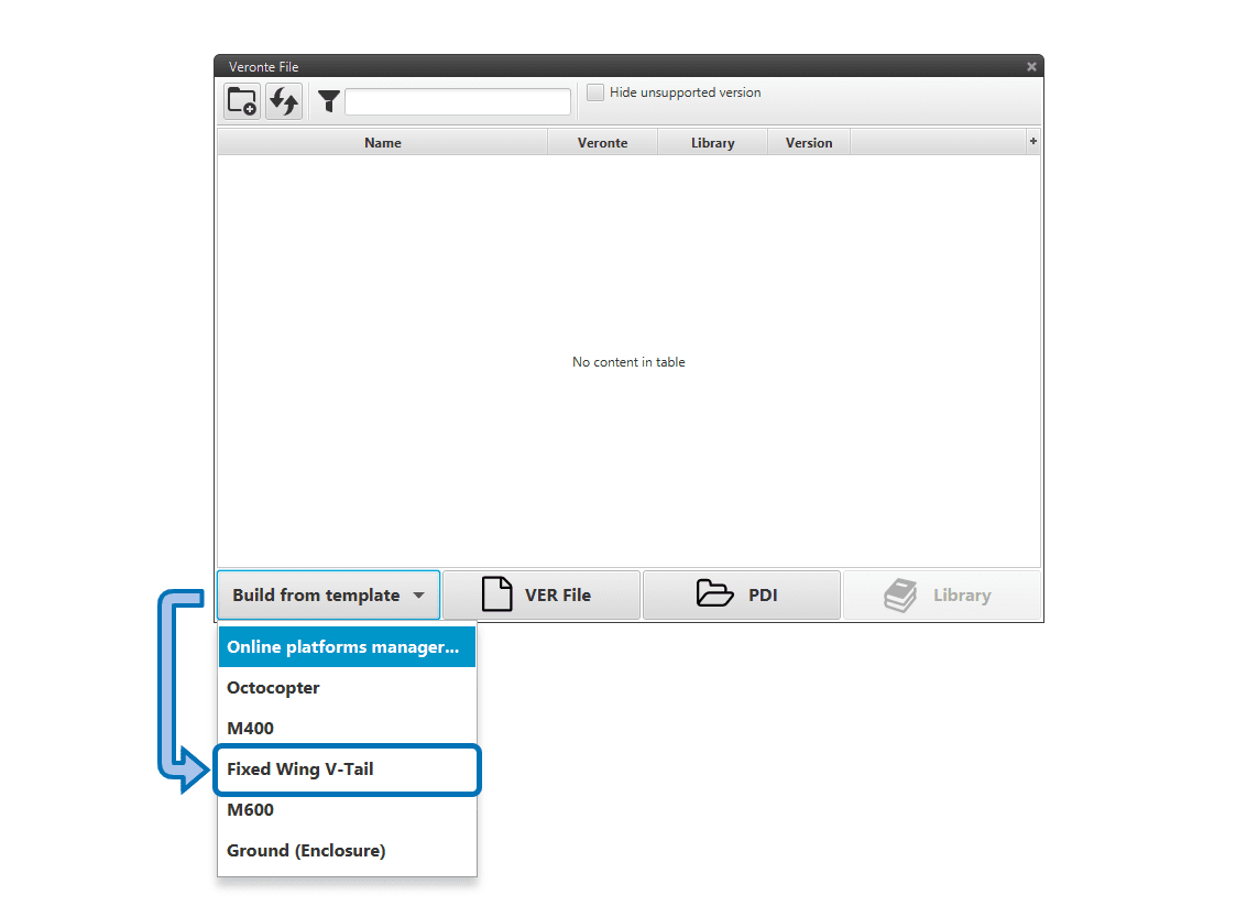
Fixed wing V-Tail template
A configuration merge and Migration windows will pop-up (see figure below). The user should accept both of them as they are. For more information on this topic go to Import Configurations.
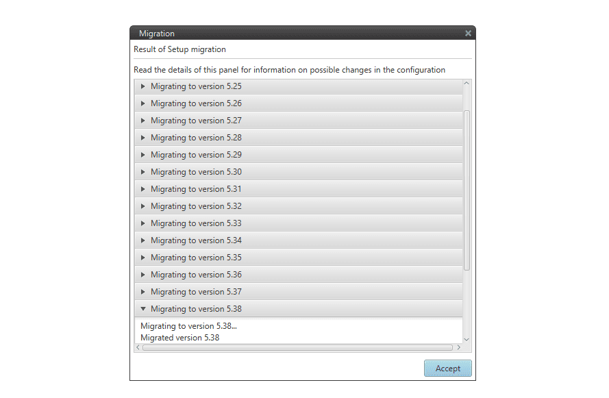
Pop-up window to end the import process
The Fixed Wing V-Tail template mission should look like this:
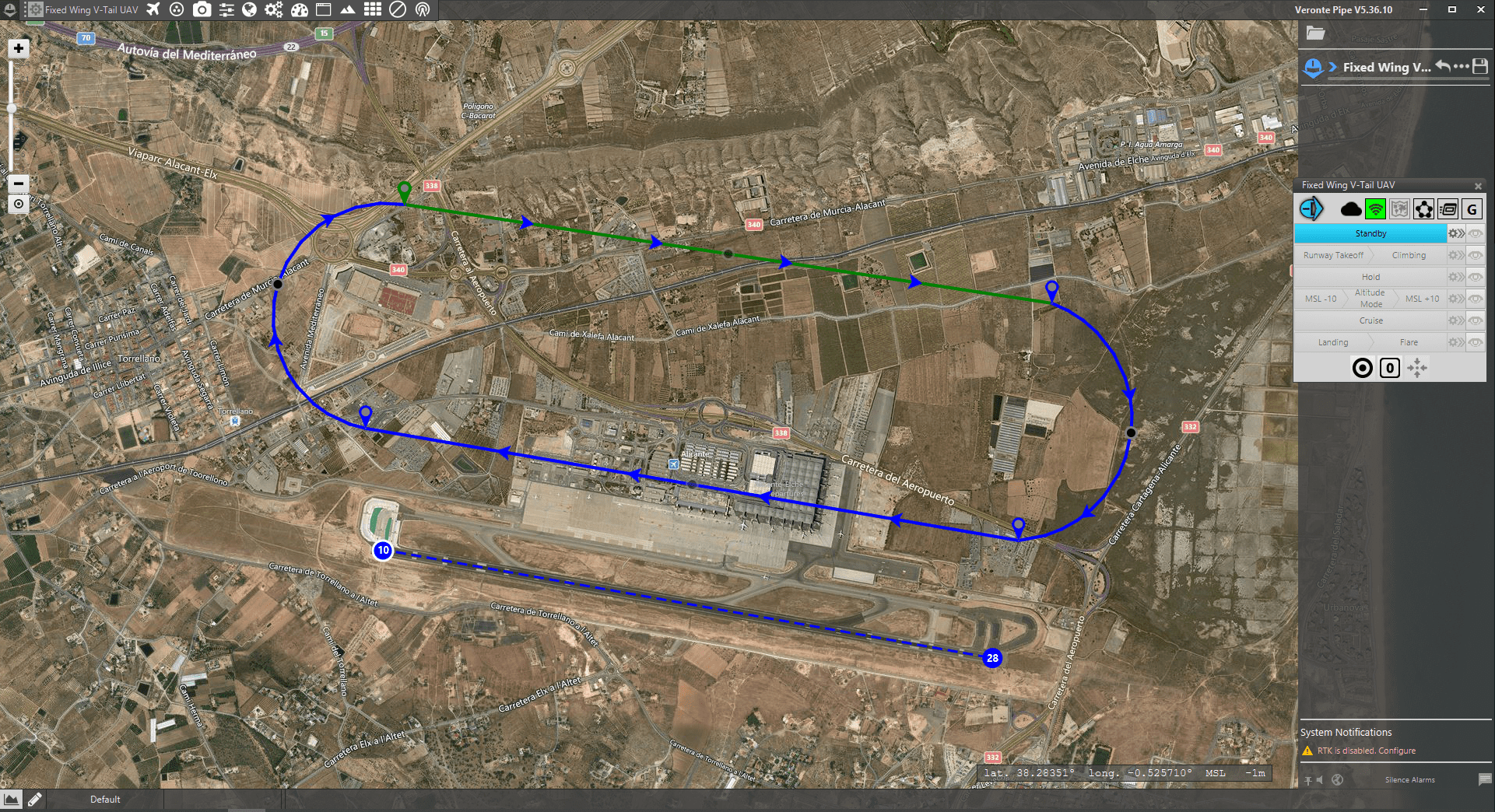
Template’s mission
Now, the user needs to open X-Plane 11 and click on New Flight. On that menu the user will select the custom-made model and Alicante as the desired location (see the figure below):
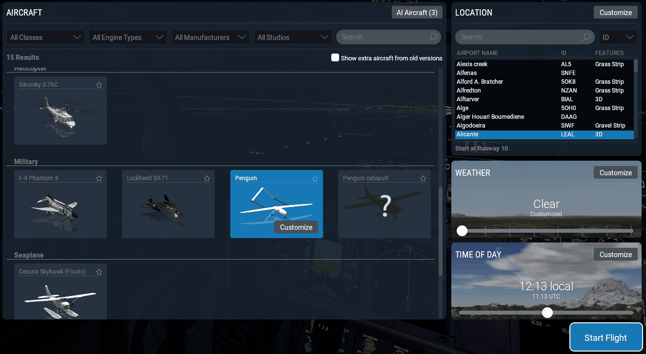
X-Plane 11: new flight
One should click on Customize in order to select the desired runway for take-off (see the figure below):
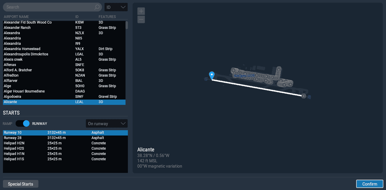
X-Plane 11: runway selection
After that the flight can already be started (click on Start Flight). The aircraft will appear at the header of runway 10 of Alicante’s airport. Once that is done, connection between X-Plane 11 and Veronte Pipe can be stablished. Go to Pipe, click on ![]() , then HIL and click on Start. Autopilot must be in the initial phase. On the contrary, click on Advanced and then on Restart Veronte. If every step was correctly done, GPS is simulated (from X-Plane) and then the UAV must be visible on Veronte Pipe map.
, then HIL and click on Start. Autopilot must be in the initial phase. On the contrary, click on Advanced and then on Restart Veronte. If every step was correctly done, GPS is simulated (from X-Plane) and then the UAV must be visible on Veronte Pipe map.

Autopilot visible on Veronte Pipe
Now the user can pass the system to Standby phase to start the flight. To do so click on the panel and the word Standby will turn green. After that, click on Runway Takeoff and the aircraft will carry on autonomously until reaching a Cruise phase. The transition between phases is defined in the Automations menu. For more infomation regarding that subject check Automations.
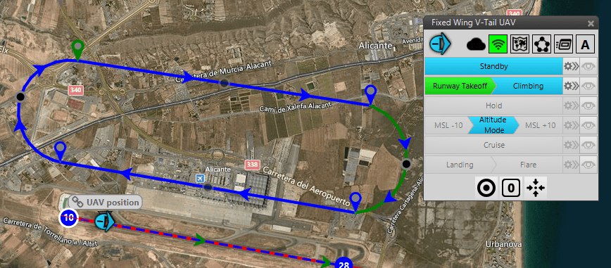
Take-off phase
The transition from take-off phase to climbing phase happens when the Indicated Air Speed (IAS) is greater than 20 m/s. The climbing phase (see figure below) automatically traces a climbing path.
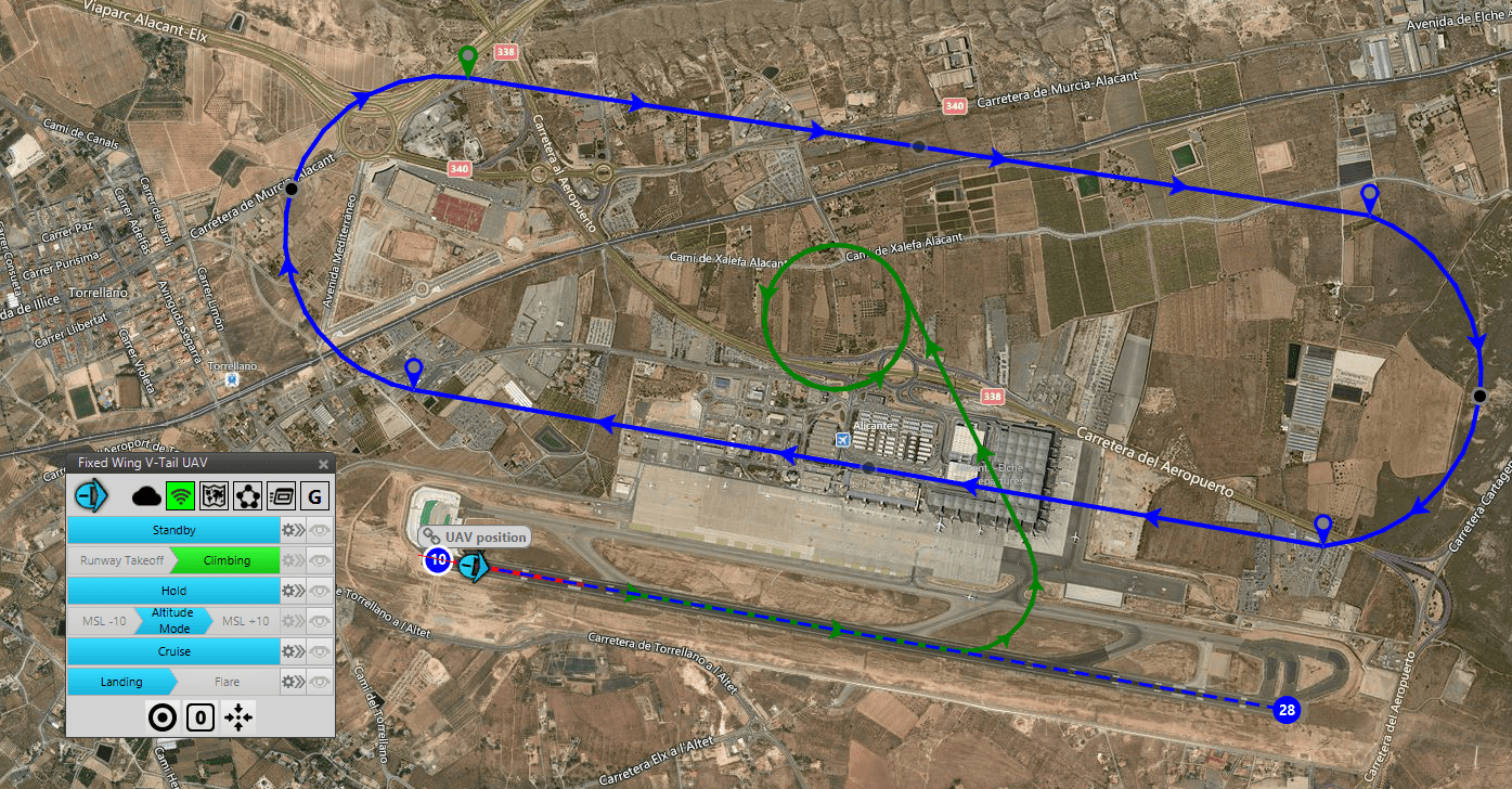
Climbing phase
But transittioning to cruise phase happens when only one condition is met: above ground level (AGL) altittude of more than 100 m.
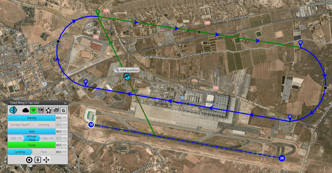
Cruise phase
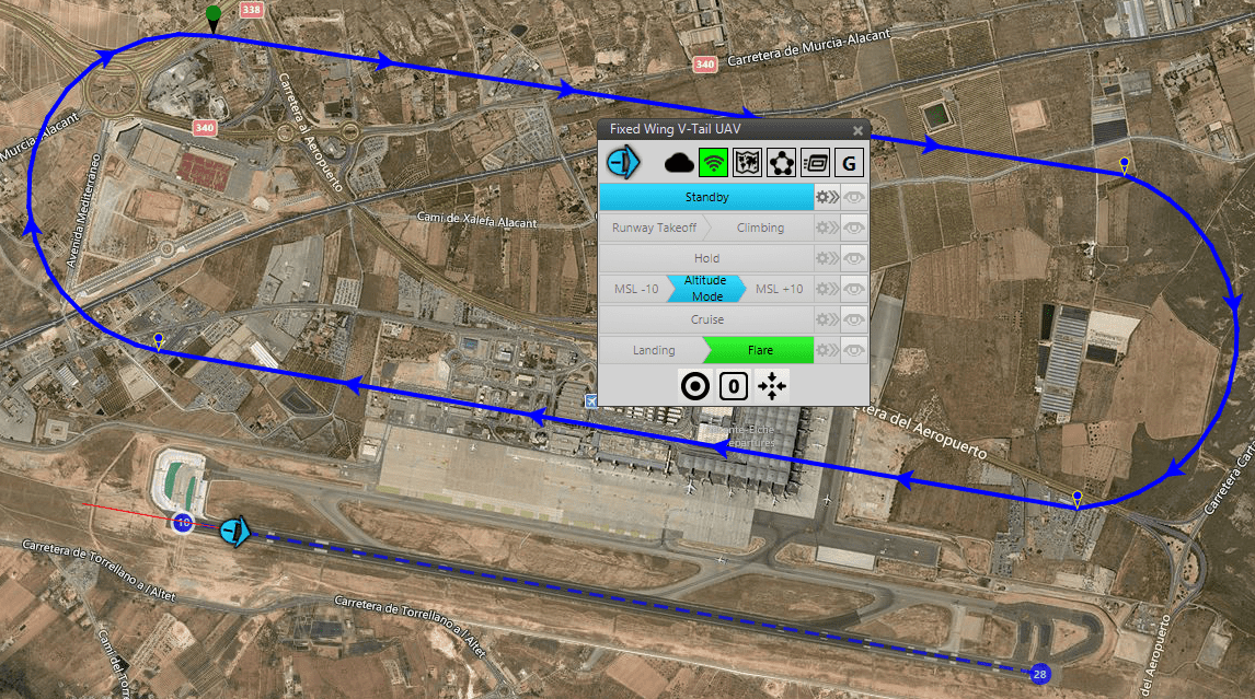
Once in cruise mode the aircraft will follow the mission displayed above in blue, being in creen the present route. Unless you define an event to motivate the entry of landing phase (a certaing flight time, a certain altitude, etc), this template does not have that part automated. Upon clicking on Landing, a landing path is automatically traced.
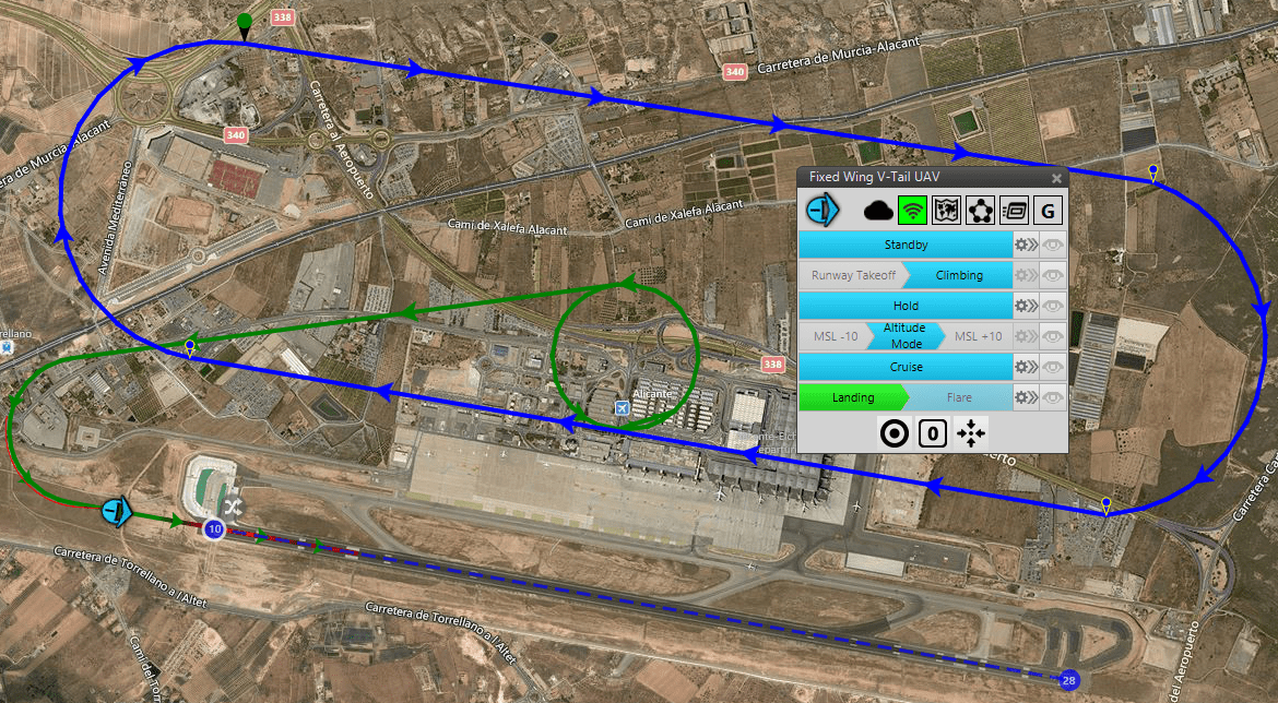
Landing phase
The condition to change from landing to flare phase is double: having an AGL smaller than 10 m and having passed by a waypoint. For more information on mission planning/design check Mission chapter.
Flare phase
After that, the aircraft will have succesfully landed and gone back to Standby phase. If the user need to adapt the flight phases to it’s model, one needs to go to the Control menu, and then go to Phases. There, parameters as take-off speed, cruise speed, among others, can be modified. For more information please check Phases definition.
All the steps above should serve as a starting point for the user to become more acquainted with HIL simulations. With the latter he or she will improve the definition and operation of the mission and the performance and control of the platform.