Aircraft Mounting
Enclosure
4xVeronte is provided using an anodized-aluminium enclosure with enhanced EMI shielding and IP protection. The approximate total weight including radio modules is 750g. The following figure show the dimensions of the enclosure. M4 screws are recommended for mounting.
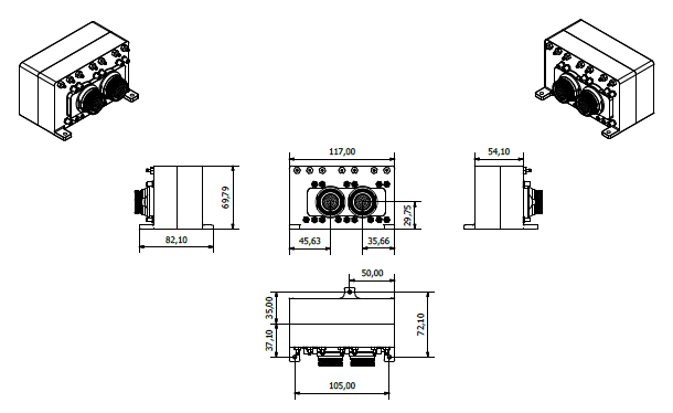
4xVeronte dimensions (mm)
Vibration Isolation
Although Veronte rejects noise and modes of vibration with internal electronic and mechanical filters, an external vibration isolation might be needed depending of the vehicle.
Veronte can be mounted in different ways in order to reject the airframe vibration if needed. One way to avoid vibration would be the use of some external structure which could be rigidly attached to the airframe and softly attached to Veronte (e.g. foam, silent blocks, etc.)
The user should take into account that wiring should be loose enough so vibrations may not find another way to enter the aircraft system.
Location
The location of 4xVeronte has no restrictions. You only need to configure its relative position with respect to the centre of mass of the aircraft and the GNSS antenna. The configuration of the location of Veronte can be easily configured using Veronte Pipe Software.
Orientation
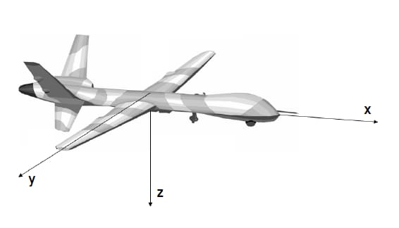
The orientation of 4xVeronte has no restrictions either. You only need to configure Veronte axes with respect to the aircraft body axes by means of a rotation matrix or a set of correspondences between axes. The configuration of the location of Veronte can be easily configured using Veronte Pipe Software.
Veronte axes are printed on the box and aircraft reference frame are defined by the standard flight dynamics conventions.
Aircraft Mounting
Connector Layout
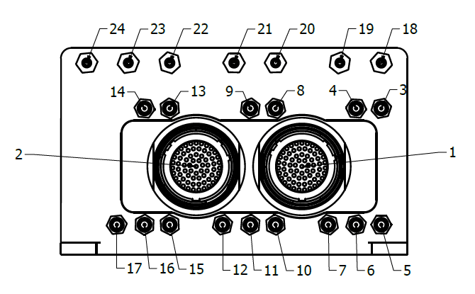
4xVeronte Connectors
Index |
Connector |
|---|---|
1 |
Redundant (Critical) connector |
2 |
Arbiter (Optional) connector |
3 |
LOS SSMA connector for Veronte 3 |
4 |
GNSS1 SSMA connector for Veronte 3 |
5 |
M2M SSMA connector for Veronte 3 |
6 |
GNSS2 SSMA connector for Veronte 3 |
7 |
TPDR (Transponder) SSMA connector for Veronte 3 |
8 |
LOS SSMA connector for Veronte 2 |
9 |
GNSS1 SSMA connector for Veronte 2 |
10 |
M2M SSMA connector for Veronte 2 |
11 |
GNSS2 SSMA connector for Veronte 2 |
12 |
TPDR (Transponder) SSMA connector for Veronte 2 |
13 |
LOS SSMA connector for Veronte 1 |
14 |
GNSS1 SSMA connector for Veronte 1 |
15 |
M2M SSMA connector for Veronte 1 |
16 |
GNSS2 SSMA connector for Veronte 1 |
17 |
TPDR (Transponder) SSMA connector for Veronte 1 |
18 |
Dynamic pressure port (Fitting 5/64in) for Veronte 3 |
19 |
Static pressure port (Fitting 5/64in) for Veronte 3 |
20 |
Dynamic pressure port (Fitting 5/64in) for Veronte 2 |
21 |
Static pressure port (Fitting 5/64in) for Veronte 2 |
22 |
Dynamic pressure port (Fitting 5/64in) for Veronte 1 |
23 |
Static pressure port (Fitting 5/64in) for Veronte 1 |
24 |
Static pressure port (Fitting 5/64in) for all Verontes |
For pressure ports, mating with clamped 2mm internal diameter flexible tubing is recommended.
The static pressure port for all Verontes sets the 4xVeronte internal cage pressure.
Mating Connectors
Index |
Connector |
Mating Connector |
|---|---|---|
3,8,13 |
RF antenna/(SSMA Jack Female) |
SSMA male Plug , low-loss cable is recommended. |
4,9,14,16,11,6 |
GNSS antenna/(SSMA Jack Female) |
SSMA male Plug, low-loss cable is recommended./Active Antenna GNSS: Gain min 15dB (to compensate signal loss in RF Cable) max 50dB, maximum noise figure 1.5dB, power supply 3.3V max current 20 mA |
10,12,14 |
M2M antenna/(SSMA Jack Female) |
SSMA male Plug, low-loss cable is recommended. |
1 |
Redundant Connector/Connector HEW.LM.368.XLNP |
Mating connector P/N: FGW.LM.368.XLCT/Mating harness is available on demand. |
2 |
Arbiter Connector/Connector HEW.LM.368.XLNP |
Mating connector P/N: FGW.LM.368.XLCT/Mating harness is available on demand. |
7,12,17 |
TPDR antenna (SSMA Jack Female) |
SSMA male Plug, low-loss cable is recommended. |
Antenna Integration
The system uses different kinds of antennas to operate that must be installed on the airframe. Here you can find some advice for obtaining the best performance and for avoiding antenna interferences.
Antenna Installation |
|---|
Maximize separation between antennas as much as possible. |
Keep it far away from alternators or other interference generators. |
Always isolate antenna ground panel from the aircraft structure. |
Make that the antenna is securely mounted. |
Always use high-quality RF wires minimising the wire length. |
Always follow the antenna manufacturer manual. |
SSMA connections shall be tightened applying 1Nm of torque |
For all-weather aircraft, insert SSMA lightning protectors. |
GNSS Antenna |
|---|
Antenna top side must point the sky. |
Install it on a top surface with direct sky view. |
Never place metallic / carbon parts or wires above the antenna. |
It is recommended to install it on top of a ground plane. |
For all-weather aircraft, insert SSMA lightning protectors. |
Pressure lines
4xVeronte has 6 pressure input lines, 3 for static pressure to determine the absolute pressure and 3 for pitot in order to determine the dynamic pressure on each internal autopilot.
Absolute pressure connection on the aircraft is mandatory while pitot port can be obviated in some aircrafts. Pitot port absence must be configured on Veronte Pipe software.
Pressure Intake |
|---|
Pressure intakes must be located in order to prevent clogging. |
Never install pressure intakes on the propeller flow. |
Design pressure tubing path in order to avoid tube constriction. |
Static Pressure |
|---|
It is not recommended to use inside fuselage pressure if it is not properly vented. |
Pitot Tube |
|---|
It is recommended to install it near the aircraft axis in order to avoid false measures during manoeuvres. |
For low-speed aircraft it is recommended at least 6,3mm tubes for preventing rain obstruction. |
Pitot tube must be installed facing the airflow in the direction of the “x” axis of the aircraft. |