Hardware Installation
Mechanical
Veronte Autopilot 4x is covered with an aluminium enclosure with enhanced EMI shielding and IP protection, with 750 g as total weight.
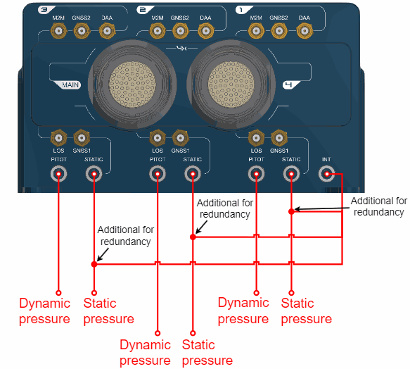
Pressure lines
Veronte Autopilot 4x has seven redundant pressure input lines; four for static pressure to determine the absolute pressure and three for pitot in order to determine the dynamic pressure.
For the fittings it is recommended to use a polyurethane tube of 2.5 mm inner diameter and 4 mm outer diameter.
-
Pressure Intake
- Pressure intakes must be located in order to prevent clogging.
- Do not install pressure intakes on the propeller flow.
- Design pressure tubing path in order to avoid tube constriction.
-
Static Pressure
- It is not recommended to use inside fuselage pressure if it is not properly vented.
-
Pitot Tube
- Pitot tube must be installed facing the airflow.
- It is recommended to install it near the aircraft's x axis in order to avoid false measures during manoeuvres.
- For low-speed aircraft it is recommended at least 6.3 mm tubes to prevent any rain obstruction.
Location
The location of Veronte Autopilot 4x has no restrictions. It is only required to configure its relative position respect to the centre of mass of the aircraft and the GNSS antenna. The configuration of the location of each Autopilot 1x can be easily configured using 1x PDI Builder.
Orientation
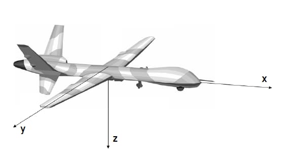
The orientation of Veronte Autopilot 4x has no restrictions either. It is only required to configure axes respect to the aircraft by means of a rotation matrix or a set of correspondences between axes. The configuration of the orientation can be easily configured using 1x PDI Builder for each Autopilot 1x.
Axes are printed on the Autopilot 4x box. Aircraft coordinates are defined by the standard aeronautical conventions, shown in the following figure.
Vibration Isolation
Although Veronte Autopilot 4x rejects noise and high-frequency vibration modes with electronic filters, there may be situations where external isolation is needed.
Autopilot 4x can be mounted in different ways in order to reject the airframe vibration, but it is recommend to use the Damping System designed for that porpuse. It covers a wide frequency range of different aircraft types.
Note
The user should take into account that wiring should be loose enough so that vibrations are not transmitted to Autopilot 4x.
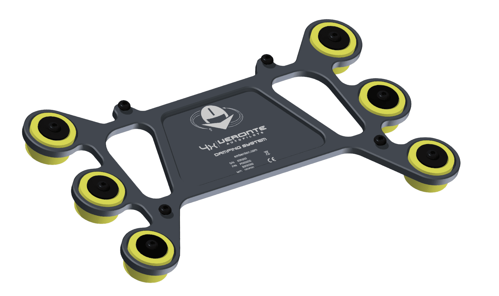
Damping System
Embention offers the Damping System as a solution to isolate Veronte Autopilot 4x from vibrations.
Important
Only effective with Autopilot 4x in horizontal position.
This damping system weighs 76 g.
Warning
The Damping System is designed for version 1.8 of Autopilot 4x.
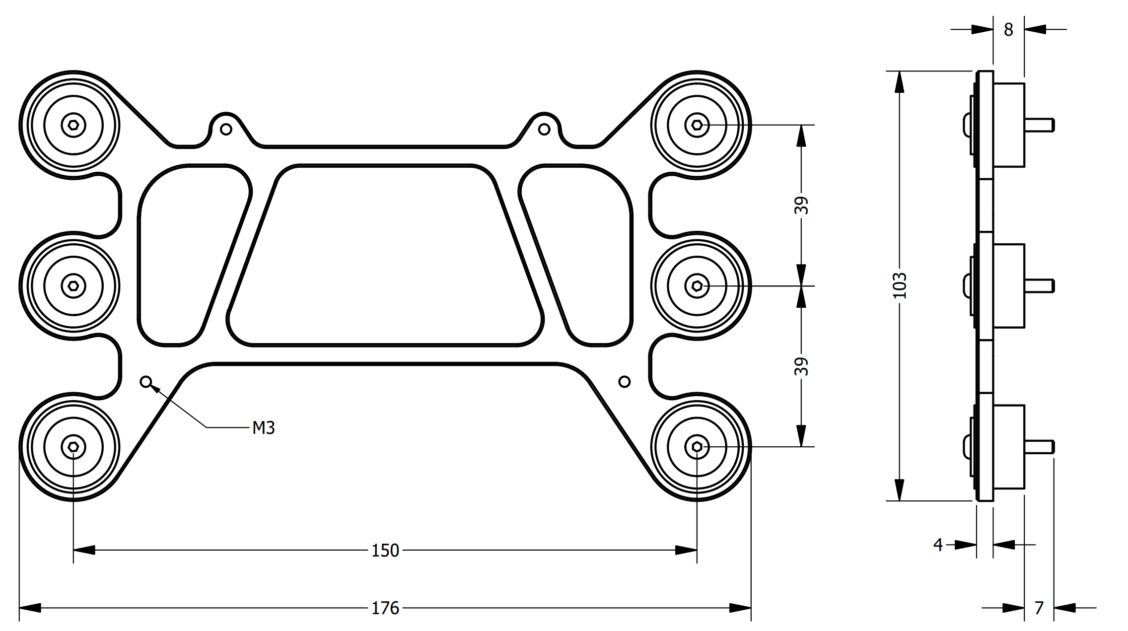
Dimensions
Assembly steps
To assembly the Damping System into a vehicle with an Autopilot 4x, read the following steps.
-
Remove the six nuts located under the platform.
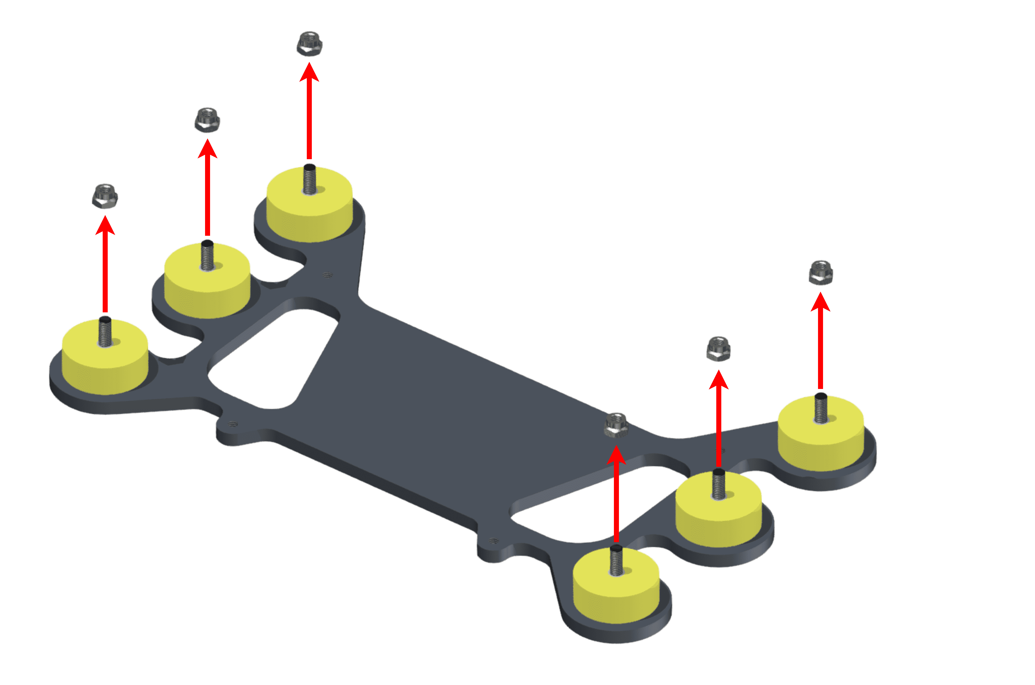
Step 1 -
Screw the platform on the aircraft frame. The included screws have M3.
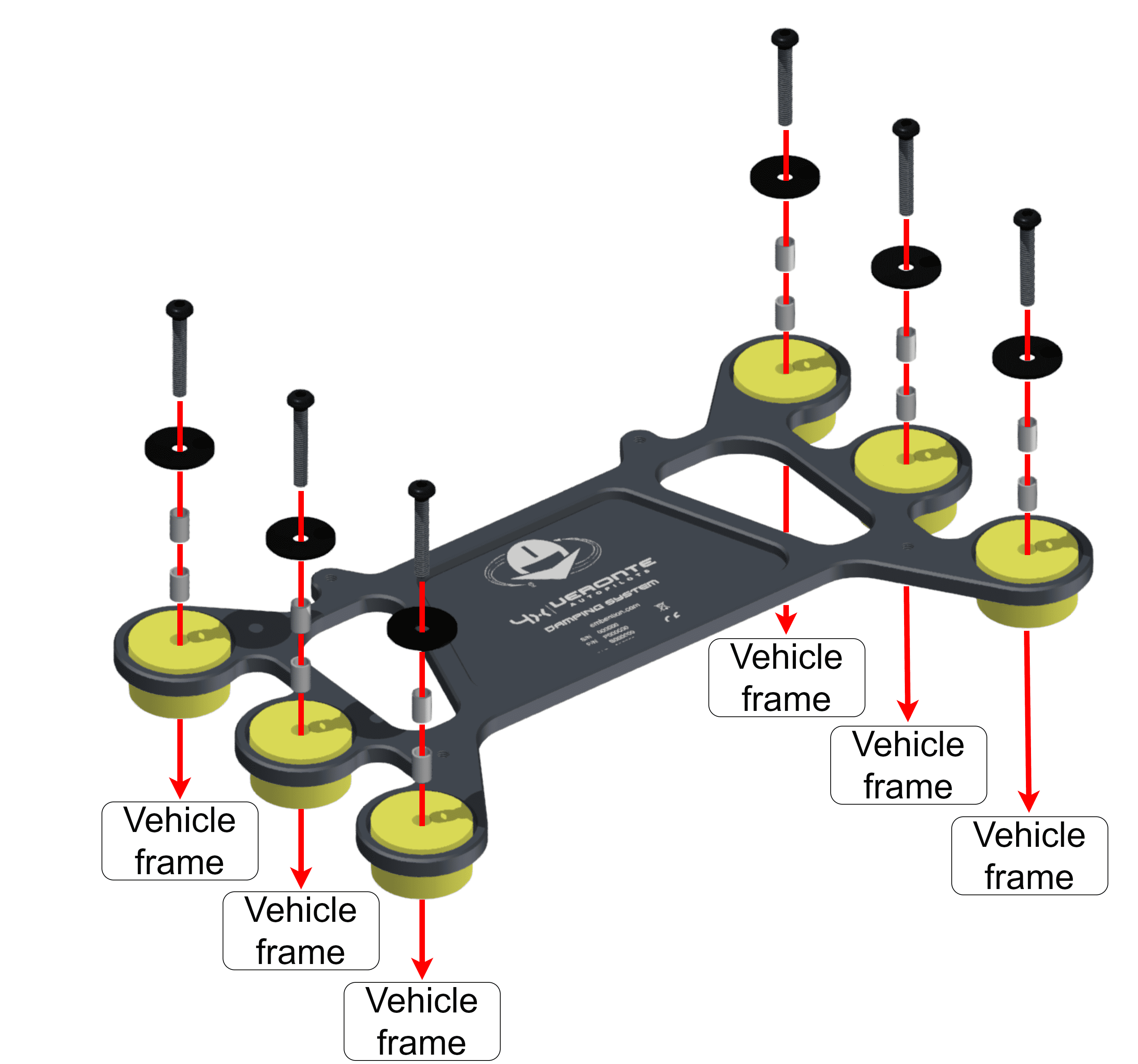
Step 2 -
Screw the Autopilot 4x on the Damping system.
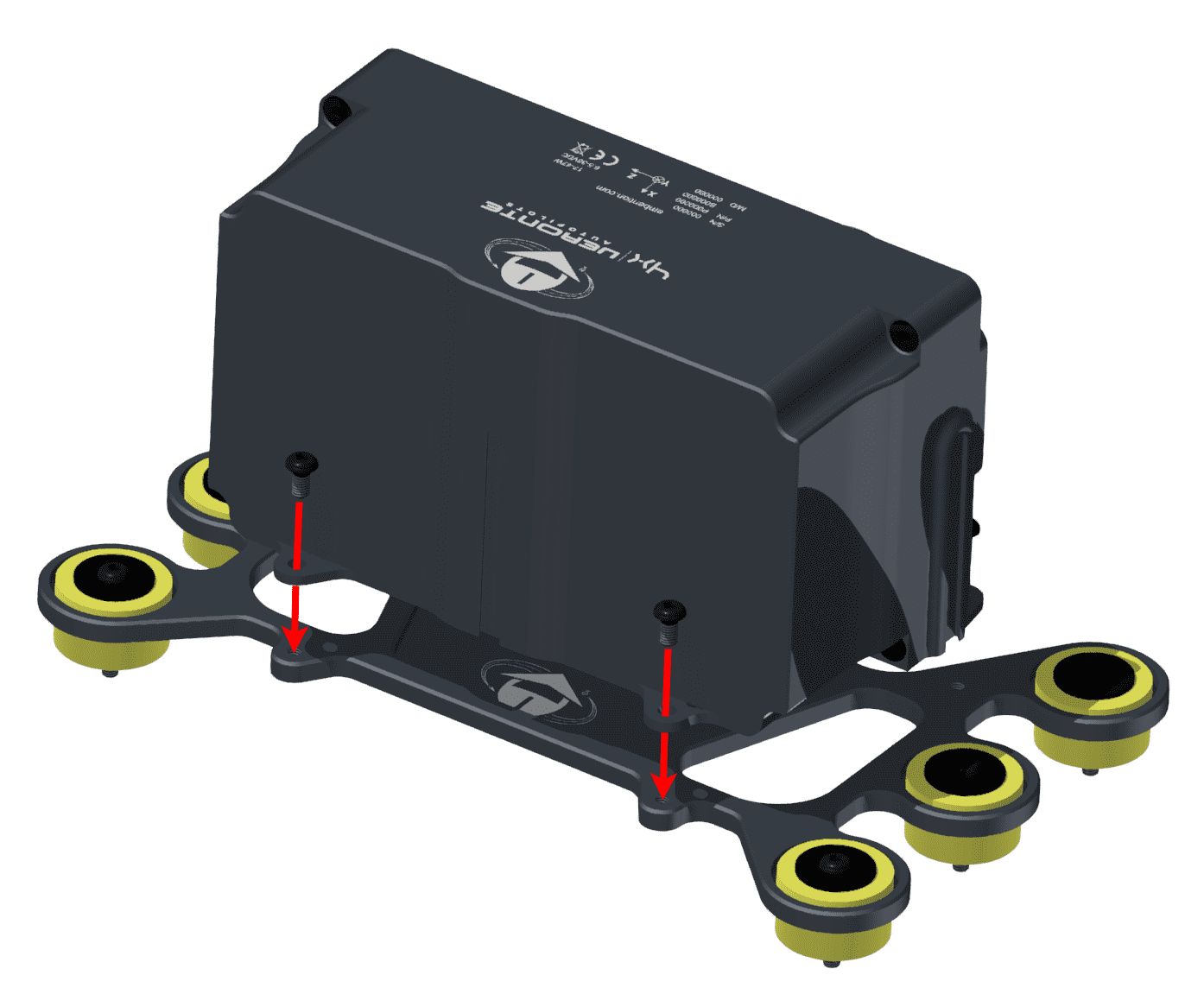
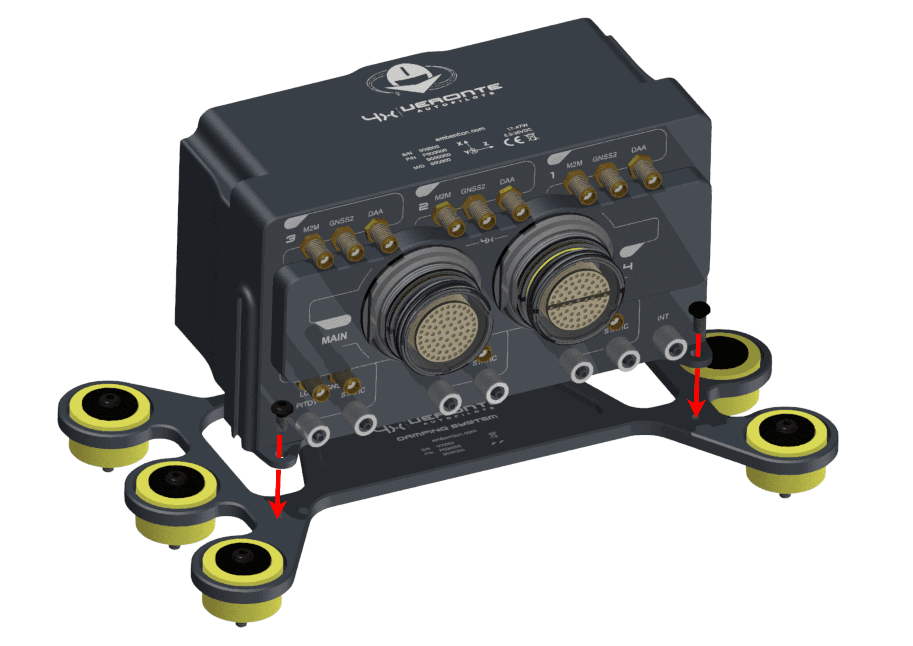
Step 3
Antenna Integration
The system uses different kinds of antenna to operate, they must be installed on the airframe. Here you can find some advice for obtaining the best performance and for avoiding antenna interferences.
-
Antenna Installation
- Maximize separation between antennas as much as possible.
- Keep antennas far away from alternators or other interference generators.
- Always isolate the antenna ground panel from the aircraft structure.
- Make sure antennas are securely mounted.
- Always use high-quality RF wires minimising the wire length.
- Always follow the antenna manufacturer manual.
- SSMA connections shall be tightened applying 1Nm of torque.
- For all-weather aircraft, insert SSMA lightning protectors.
-
GNSS Antenna
- Antenna top side must point to the sky.
- Install them on a top surface with direct sky view.
- Never place wires or parts made of memetal or carbon above the antenna.
- It is recommended to install antennas on a small ground plane.
- For all-weather aircrafts, insert SSMA lightning protectors.
-
Recommended specifications for GNSS antennas
Specifications Range Antenna frequency L1 1561.098 MHz to 1602 MHz Antenna frequency L2 1207.14 MHz to 1246 MHz Amplifier gain 17 dB to 35 dB Out-of-band rejection 40 dB
Note
Higher values are preferable.
30 dB is considered the minimum acceptable value.Polarization RHCP (Right-Hand Circular Polarization) Minimum supply voltage 2.7 V to 3.3 V Maximum supply current 50 mA
Electrical
Power supply
Autopilot 4x can use unregulated DC (6.5 V to 36 V) for the internal Veronte autopilots and also for the Management Board. All power supply pins are not common. It is possible to supply them with different voltages since they are internally protected with diodes. Nonetheless, all power supply pins must be connected to a power supply, in order to guarantee that Autopilot 4x will work in case of failing one of them. These pins are summarized in the following table:
| Connector | PIN | Signal |
|---|---|---|
| Main Connector | 68 | BAT_0 |
| 67 | BAT_1 | |
| 64 | BAT_2 | |
| Arbiter Connector | 68 | VCC_ARBITER |
LiPo batteries between 2S and 8S can be used without voltage regulation. Remaining battery can be controlled by the internal voltage sensor and by configuring the voltage warnings on the PC application.
For higher voltage installations, voltage regulators must be used. For dimensioning voltage regulators take into account that a blocked servo can activate regulator thermal protection.
Warning
Power Veronte Autopilot 4x out of the given range can cause irreversible damage to the system. Please read carefully the manual before powering the system.
Autopilots and servos can be powered by the same or different batteries. In case there are more than one battery on the system, a single point ground union is needed to ensure a good performance. The ground signal should be isolated from other system ground references (e.g. engines).
It is recommendable to use independent switches for autopilot and motor/actuators. During the system initialization, PWM signal will be fixed to low level (0V), please make sure that actuators/motor connected support this behavior before installing a single switch for the whole system.
Power Domains
Veronte Autopilot 4x has two internal power domains (A and B). Power domains are isolated each other; hence, if one of them fails, the other one will remain operational. Many of the signals on the pinout are powered by one power domain.
Separated power domains allow to manage redundancy against internal power failures. For example, if the aircraft requires to measure a critical temperature of an external device, the user can use two different analog sensors and connect them to analog inputs of different power domains. One option for this example is connecting them to pin 38 (domain A) and pin 22 (domain B). Thus, if there is an internal failure and power domain A fails, the autopilot will still read measurements from pin 22.
Any power supply pin (pins 64, 67 and 68 from Main Connector and pin 68 from Arbiter Connector) powers both domains. Nonetheles, this is independent of the power supply for each internal Autopilot 1x. Since pins 64, 67 and 68 from Main Connector power one single autopilot (appart from power domains).
Pinout
Warning
Pins can transfer 2 A as maximum current.
Warning
Check the pin number before connecting. The color code is repeated 3 times due to the amount of pins. First section (yellow) corresponds to pins 1-30, the second section (blue) to pins 31-60 and the third one (red) to pins 61-68. Pin number increases following the black line of the pictures above: counterclockwise for the connector and clockwise for the plug.
Main Connector pinout
| PIN | Signal | Type | Internal Power Domain | Description |
|---|---|---|---|---|
| 1 | I/O_0_MUXED | I/O | A | MUXED PWM / Digital I/O signal (0-3.3V)
Warning
Each pin withstands a maximum current of 1.65 mA. |
| 2 | I/O_1_MUXED | I/O | B | |
| 3 | I/O_2_MUXED | I/O | A | |
| 4 | I/O_3_MUXED | I/O | B | |
| 5 | I/O_4_MUXED | I/O | A | |
| 6 | I/O_5_MUXED | I/O | B | |
| 7 | I/O_6_MUXED | I/O | A | |
| 8 | I/O_7_MUXED | I/O | B | |
| 9 | GND* | GROUND | Ground pin for signals 1-8 | |
| 10 | I/O_8_MUXED | I/O | A | MUXED PWM / Digital I/O signal (0-3.3V)
Warning
Each pin withstands a maximum current of 1.65 mA. |
| 11 | I/O_9_MUXED | I/O | B | |
| 12 | I/O_10_MUXED | I/O | A | |
| 13 | I/O_11_MUXED | I/O | B | |
| 14 | I/O_12_MUXED | I/O | A | |
| 15 | I/O_13_MUXED | I/O | B | |
| 16 | I/O_14_MUXED | I/O | A | |
| 17 | I/O_15_MUXED | I/O | B | |
| 18 | GND* | GROUND | Ground pin for signals 10-17 | |
| 19 | MUXED_RS232_TX | OUTPUT | A | MUXED RS-232 output |
| 20 | MUXED_RS232_RX | INPUT | A | REDUNDANT RS-232 input |
| 21 | V2_USB_DP | I/O | Autopilot 2 USB positive data line | |
| 22 | ANALOG_3 | INPUT | B | REDUNDANT analog input (0-36V) |
| 23 | ANALOG_4 | INPUT | B | |
| 24 | V2_USB_DN | I/O | Autopilot 2 USB negative data line | |
| 25 | CANA_ARB_P | I/O | A | CAN-bus interface. It supports data rates up to 1 Mbps. A 120 Ohm Zo is required and twisted pair is recommended. |
| 26 | CANA_ARB_N | I/O | A | |
| 27 | GND* | GROUND | GROUND pin for buses (except USB) | |
| 28 | CANB_ARB_P | I/O | CAN-bus interface. It supports data rates up to 1 Mbps. A 120 Ohm Zo is required and twisted pair is recommended. |
|
| 29 | CANB_ARB_N | I/O | ||
| 30 | V2_USB2_GND | GROUND | Autopilot 2 USB ground | |
| 31 | I2C_CLK | OUTPUT | A | MUXED Clock line for I2C bus (0.3V to 3.3V) |
| 32 | I2C_DATA | I/O | A | MUXED data line for I2C bus |
| 33 | GND* | GROUND | Ground for 3.3V power supply | |
| 34 | V1_ARB_TX | OUTPUT | Microcontroller UART transmitter for Autopilot 1 | |
| 35 | V1_ARB_RX | INPUT | Microcontroller UART receiver for Autopilot 1 | |
| 36 | V2_ARB_TX | OUTPUT | Microcontroller UART transmitter for Autopilot 2 | |
| 37 | V2_ARB_RX | INPUT | Microcontroller UART receiver for Autopilot 2 | |
| 38 | ANALOG_0 | INPUT | A | REDUNDANT analog input (0-36V) |
| 39 | ANALOG_1 | INPUT | A | |
| 40 | ANALOG_2 | INPUT | A | |
| 41 | GND* | GROUND | Ground signal for buses | |
| 42 | V3_USB_DP | I/O | Autopilot 3 USB positive data line | |
| 43 | V3_USB_DN | I/O | Autopilot 3 USB negative data line | |
| 44 | GND* | GROUND | Ground signal for buses | |
| 45 | V3_ARB_TX | OUTPUT | Microcontroller UART transmitter for Autopilot 3 | |
| 46 | V3_ARB_RX | INPUT | Microcontroller UART receiver for Autopilot 3 | |
| 47 | GND* | GROUND | Ground signal for buses | |
| 48 | ||||
| 49 | V3_USB3_GND | GROUND | Autopilot 3 USB ground | |
| 50 | OUT_RS485_P | OUTPUT | B | MUXED non-inverted output RS-485 bus |
| 51 | OUT_RS485_N | OUTPUT | B | MUXED inverted output RS-485 bus |
| 52 | IN_RS485_N | INPUT | REDUNDANT inverted inout RS-485 bus | |
| 53 | IN_RS485_P | INPUT | REDUNDANT non-inverted input RS-485 bus | |
| 54 | RS485_GND | GROUND | Ground for RS-485 bus | |
| 55 | EQEP_A | INPUT | A for autopilots 1 and 2 B for autopilot 3 |
Encoder quadrature redundant input A (0-5V) |
| 56 | EQEP_B | INPUT | Encoder quadrature redundant input B (0-5V) | |
| 57 | EQEP_S | INPUT | Encoder strobe redundant input (0-5V) | |
| 58 | EQEP_I | INPUT | Encoder index redundant input (0-5V) | |
| 59 | GND* | GROUND | Autopilot 3 ground pin | |
| 60 | V1_USB_DP | I/O | Autopilot 1 USB positive data line | |
| 61 | V1_USB_DN | I/O | Autopilot 1 USB negative data line | |
| 62 | V1_USB1_GND | GROUND | Autopilot 1 USB ground | |
| 63 | GND* | GROUND | Ground signal for buses | |
| 64 | BAT_2 | POWER | Autopilot 3 power supply (6.5 to 36V) | |
| 65 | GND* | GROUND | Autopilot 2 ground pin | |
| 66 | GND* | GROUND | Autopilot 1 ground pin | |
| 67 | BAT_1 | POWER | Autopilot 2 power supply (6.5 to 36V) | |
| 68 | BAT_0 | POWER | Autopilot 1 power supply (6.5 to 36V) |
Warning
Common grounds are marked with *.
Note
MUXED (multiplexed) signals are connected to the Autopilot 1x decided by the Management Board, then only the selected autopilot is connected to MUXED pins.
REDUNDANT signals are connected to the three inner autopilots, so all of them receive the same REDUNDANT signals.
To know the differences between version 1.2 and 1.8 (this one), read the Pinout changes from Autopilot 4x 1.2 - Hardware Changelog section of the present manual.
Arbiter Connector pinout
Although being the same component, Main Connector and Arbiter connector are polarized differently, but they have different mechanical connections to avoid wiring swapping.
| PIN | Signal | Type | Internal Power Domain | Description |
|---|---|---|---|---|
| 1 | I/O_0_EXTERNAL | I/O | A | External MUXED PWM / Digital I/O signal (0-3.3V). In case of employing an additional external autopilot, its pins I/XX must be connected here. Each signal I/O_XX_EXTERNAL will be sent to I/XX of Main Connector if the arbiter commands it.
Warning
Input current must be limited to 25 mA for each I/O EXTERNAL pin. |
| 2 | I/O_1_EXTERNAL | I/O | B | |
| 3 | I/O_2_EXTERNAL | I/O | A | |
| 4 | I/O_3_EXTERNAL | I/O | B | |
| 5 | I/O_4_EXTERNAL | I/O | A | |
| 6 | I/O_5_EXTERNAL | I/O | B | |
| 7 | I/O_6_EXTERNAL | I/O | A | |
| 8 | I/O_7_EXTERNAL | I/O | B | |
| 9 | I/O_8_EXTERNAL | I/O | A | |
| 10 | I/O_9_EXTERNAL | I/O | B | |
| 11 | I/O_10_EXTERNAL | I/O | A | |
| 12 | I/O_11_EXTERNAL | I/O | B | |
| 13 | ARBITER_ANALOG_7 | INPUT | Arbiter analog input (0-36V) | |
| 14 | EXTERNAL_ANALOG_0 | OUTPUT | A | External analog signal (0-3V). This is the analog signal from ANALOG_0 on Main Connector, which is reduced from 0-36V to 0-3V. |
| 15 | EXTERNAL_ANALOG_1 | OUTPUT | A | External analog signal (0-3V). This is the analog signal from ANALOG_1 on Main Connector, which is reduced from 0-36V to 0-3V. |
| 16 | EXTERNAL_ANALOG_2 | OUTPUT | A | External analog signal (0-3V). This is the analog signal from ANALOG_2 on Main Connector, which is reduced from 0-36V to 0-3V. |
| 17 | EXTERNAL_ANALOG_3 | OUTPUT | B | External analog signal (0-3V). This is the analog signal from ANALOG_3 on Main Connector, which is reduced from 0-36V to 0-3V. |
| 18 | FTC_VOTING_B | OUTPUT | B | This pin is an open drain output (0 - 48V), which is open or connected to GND depending on the FTS signals of the Autopilots 1x.
This logic is implemented at the Voting Stage, explained in detail in the Flight Termination System section of this manual. Use this pin for an emergency device; for example the ground of a relay that activates a parachute. FTC_VOTING_A (pin 53) and FTC_VOTING_B (pin 18) do the same function, but they have dissimilarity. |
| 19 | EXT_RS232_TX | INPUT | A | In case of employing an additional external autopilot, its pin RS 232 TX must be connected here. If arbiter decides to multiplex this signal, it will be transmitted to MUXED_RS232_TX on Main Connector with RS232 protocol. |
| 20 | EXT_RS232_RX | OUTPUT | A | In case of employing an additional external autopilot, its pin RS 232 RX must be connected here. If arbiter decides to multiplex this signal, it will be transmitted to MUXED_RS232_TX on Main Connector with RS232 protocol. |
| 21 | IN_RS485_P | OUTPUT | This pin is connected with IN_RS485_P from Main Connector | |
| 22 | IN_RS485_N | OUTPUT | This pin is connected with IN_RS485_N from Main Connector | |
| 23 | EXT_OUT_RS485_P | INPUT | B | In case of employing an additional external autopilot, its pin OUT_RS485_P must be connected here. If arbiter decides to multiplex this signal and EXT_DETECT of Arbiter Connector is connected to GND, it will be transmitted to OUT_RS485_P on Main Connector with RS232 protocol. |
| 24 | EXT_OUT_RS485_N | INPUT | B | In case of employing an additional external autopilot, its pin OUT_RS485_N must be connected here. If arbiter decides to multiplex this signal and EXT_DETECT of Arbiter Connector is connected to GND, it will be transmitted to OUT_RS485_N on Main Connector with RS232 protocol. |
| 25 | CANA_P_ARB_A | I/O | This pin is connected with CANA_ARB_P from Main Connector | |
| 26 | CANA_N_ARB_A | I/O | This pin is connected with CANA_ARB_N from Main Connector | |
| 27 | ARBITER_ANALOG_8 | INPUT | Arbiter analog input (0-36V) | |
| 28 | CANB_P_ARB_B | I/O | This pin is connected with CANB_ARB_P from Main Connector | |
| 29 | CANB_N_ARB_B | I/O | This pin is connected with CANB_ARB_N from Main Connector | |
| 30 | OUT_RS485_ARB_P | OUTPUT | A | Non-inverted output for arbiter A RS-485 bus |
| 31 | OUT_RS485_ARB_N | OUTPUT | A | Inverted output for arbiter A RS-485 bus |
| 32 | IN_RS485_ARB_N | INPUT | A | Inverted output for arbiter A RS-485 bus |
| 33 | IN_RS485_ARB_P | INPUT | A | Non-inverted input for arbiter A RS-485 bus |
| 34 | TX_OUT_P | OUTPUT | A | Arbiter A ARINC positive output |
| 35 | TX_OUT_N | OUTPUT | A | Arbiter A ARINC negative output |
| 36 | RIN1_ARINC_P | INPUT | A | Arbiter A ARINC positive input |
| 37 | RIN1_ARINC_N | INPUT | A | Arbiter A ARINC negative input |
| 38 | GND* | GROUND | Ground pin for buses | |
| 39 | SCL_A_OUT_ARB | OUTPUT | A | Clock signal for arbiter A I2C bus |
| 40 | SDA_A_OUT_ARB | I/O | A | Data signal for arbiter A I2C bus |
| 41 | DSP_232_RX_B | INPUT | A | Arbiter A RS-232 input B |
| 42 | DSP_232_TX_B | OUTPUT | A | Arbiter A RS-232 output B |
| 43 | DSP_232_RX_A | INPUT | A | Arbiter A RS-232 input A |
| 44 | DSP_232_TX_A | OUTPUT | A | Arbiter A RS-232 output A |
| 45 | GND* | GROUND | Ground pin for analog signals | |
| 46 | ARBITER_ANALOG_0 | INPUT | A | Arbiter A analog input (0-36V) |
| 47 | ARBITER_ANALOG_1 | INPUT | A | |
| 48 | ARBITER_ANALOG_2 | INPUT | A | |
| 49 | ARBITER_ANALOG_3 | INPUT | A | |
| 50 | ARBITER_ANALOG_4 | INPUT | A | |
| 51 | ARBITER_ANALOG_5 | INPUT | A | |
| 52 | ARBITER_ANALOG_6 | INPUT | A | |
| 53 | FTC_VOTING_A | OUTPUT | A | This pin is an open drain output (0 - 48V), which is open or connected to GND depending on the FTS signals of the Autopilots 1x.<
This logic is implemented at the Voting Stage, explained in detail in the Flight Termination System section of this manual. Use this pin for an emergency device; for example the ground of a relay that activates a parachute. FTC_VOTING_A (pin 53) and FTC_VOTING_B (pin 18) do the same function, but they have dissimilarity. |
| 54 | GPIO_8_ARB | I/O | A | Arbiter A PWM / digital I/O signal (0-3.3V) |
| 55 | GPIO_9_ARB | I/O | A | |
| 56 | WD_EXT | INPUT | A | Watchdog signal from external autopilot to arbiter A (0-3.3V) |
| 57 | EXT_DETECT | INPUT | A | Connect to GND if external autopilot is connected, otherwise keep open |
| 58 | GND* | GROUND | Ground signal for GPIO | |
| 59 | GPIO_0_ARB | I/O | A | Arbiter A PWM / digital I/O signal (0-3.3V) |
| 60 | GPIO_1_ARB | I/O | A | |
| 61 | GPIO_2_ARB | I/O | A | |
| 62 | GPIO_3_ARB | I/O | A | |
| 63 | GPIO_4_ARB | I/O | A | |
| 64 | SEL_AP | OUTPUT | A | CAP signal indicating the AP selected |
| 65 | FTS1_OUT | OUTPUT | A | Deadman signal from comicro |
| 66 | FTS2_OUT | OUTPUT | A | System OK bit |
| 67 | GND* | GROUND | Management Board ground | |
| 68 | VCC_ARBITER | POWER | Power supply for Management Board (6.5 to 36 V) |
Warning
Common grounds are marked with *.
Important
Apart from CAN buses, all communications are established only with arbiter A (I2C, RS-232, RS-485 and ARINC).
To know the differences between version 1.2 and 1.8 (this one), read the Pinout changes from Autopilot 4x 1.2 - Hardware Changelog section of the present manual.
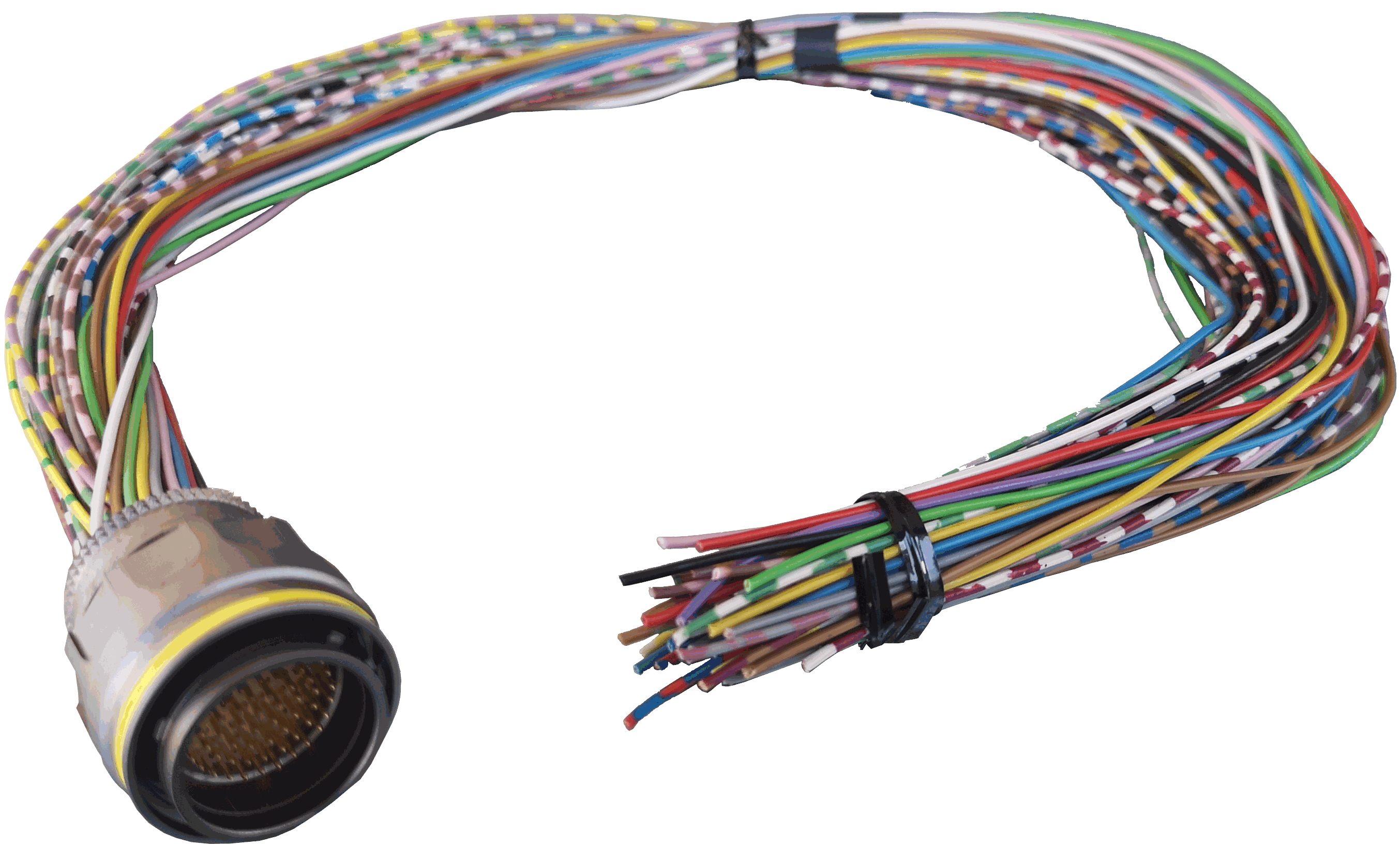
Harnesses
A wire harness is a structured assembly of cables and connectors used to organize and manage wiring in electrical and electronic systems. It is designed to ensure a tidy and secure installation of cables, preventing tangles, electromagnetic interference, and facilitating maintenance.
Veronte Autopilot 4x 1.8 has the following compatible harnesses:
| For Main Connector | |
|---|---|
| Veronte Harness Blue 68P | Dev Harness 4x 1.8 |
 |
 |
| Harness available on demand with the Embention reference P001114 | Harness available on demand with the Embention reference P007695 |
| For Connector 4: Veronte Harness Yellow 68P | |
 |
|
| Harness available on demand with the Embention reference P001118 | |
Dimensions
- Harness Blue/Yellow 68P wire gauge: 22 AWG
- Cables lenght: 52 cm
-
Harness plug dimensions:
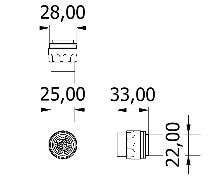
Connector FGW.LM.368.XLCT/FGR.LM.368.XLCT dimensions (cm)
Pinout

Veronte Harness Blue/Yellow 68P
- The pinout of the Veronte Harness Blue 68P is the same as the Main Connector pinout above. The color code of the harness wires is given below.
- The pinout of the Veronte Harness Yellow 68P is the same as the Arbiter Connector pinout above. The color code of the harness wires is given below.
Warning
Check the pin number before connecting. The color code is repeated 3 times due to the amount of pins. First section (yellow) corresponds to pins 1-30, the second section (blue) to pins 31-60 and the third one (red) to pins 61-68. Pin number increases following the black line of the pictures above: counterclockwise for the connector and clockwise for the plug.
| PIN | Color Code | PIN | Color Code |
|---|---|---|---|
| 1 | White | 35 | Gray |
| 2 | Brown | 36 | Pink |
| 3 | Green | 37 | Blue |
| 4 | Yellow | 38 | Red |
| 5 | Gray | 39 | Black |
| 6 | Pink | 40 | Violet |
| 7 | Blue | 41 | Gray - Pink |
| 8 | Red | 42 | Red - Blue |
| 9 | Black | 43 | White - Green |
| 10 | Violet | 44 | Brown - Green |
| 11 | Gray - Pink | 45 | White - Yellow |
| 12 | Red - Blue | 46 | Yellow - Brown |
| 13 | White - Green | 47 | White - Gray |
| 14 | Brown - Green | 48 | Gray - Brown |
| 15 | White - Yellow | 49 | White - Pink |
| 16 | Yellow - Brown | 50 | Pink - Brown |
| 17 | White - Gray | 51 | White - Blue |
| 18 | Gray - Brown | 52 | Brown - Blue |
| 19 | White - Pink | 53 | White - Red |
| 20 | Pink - Brown | 54 | Brown - Red |
| 21 | White - Blue | 55 | White - Black |
| 22 | Brown - Blue | 56 | Brown - Black |
| 23 | White - Red | 57 | Gray - Green |
| 24 | Brown - Red | 58 | Yellow - Green |
| 25 | White - Black | 59 | Pink - Green |
| 26 | Brown - Black | 60 | Yellow - Pink |
| 27 | Gray - Green | 61 | White |
| 28 | Yellow - Green | 62 | Brown |
| 29 | Pink - Green | 63 | Green |
| 30 | Yellow - Pink | 64 | Yellow |
| 31 | White | 65 | Gray |
| 32 | Brown | 66 | Pink |
| 33 | Green | 67 | Blue |
| 34 | Yellow | 68 | Red |
Dev Harness 4x 1.8
The pinout of this harness is the same as the Main Connector pinout above. In addition, this harness has some connectors already implemented for easy operation. Below is detailed information on which pins these connectors are connected to:
| Connector | PIN | Signal |
|---|---|---|
| Main VCC 1 | 66 | GND |
| 68 | BAT_0 | |
| Main VCC 2 | 65 | GND |
| 67 | BAT_1 | |
| Main VCC 3 | 59 | GND |
| 64 | BAT_2 | |
| RS232 connector | 18 | GND |
| 19 | MUXED_RS232_TX | |
| 20 | MUXED_RS232_RX | |
| Maintenance button | 31 | I2C_CLK |
| 32 | I2C_DATA | |
| Jack connector | 47 | GND |
| 55 | EQEP_A | |
| USB 1 | 60 | V1_USB_DP |
| 61 | V1_USB_DN | |
| 62 | V1_USB1_GND | |
| USB 2 | 21 | V2_USB_DP |
| 24 | V2_USB_DN | |
| 30 | V2_USB2_GND | |
| USB 3 | 42 | V3_USB_DP |
| 43 | V3_USB_DN | |
| 49 | V3_USB3_GND |
Flight Termination System (FTS)
The Flight Termination System determines the behavior of Autopilot 4x in case of severe failure. There are FTS output signals of 4x for failures of Autopilots 1x (FTC_VOTING_A and FTC_VOTING_B) and for failure of the Arbitration system (FTS1_OUT and FTS2_OUT).
Autopilots 1x failure - Voting Stage
Autopilot 4x FTS works based on a Voting Stage, a simple hardware circuit made of logic gates, which analyzes the FTS signals of each Autopilot 1x in order to determine if terminating the mission or not.
The FTS signals of Autopilots 1x, which correspond with the voting signals considered in the Voting Stage, are the following:

- Pin 63 - FTS_OUT_MPU: Its output is 0 V when the system is working as expected and 3.3 V when some error is detected.
- Pin 64 - FTS2_OUT_MPU: Its output is 0 V when the system is working as expected and 3.3 V when some error is detected.
- Pin 49 - FTS3_OUT_MPU: MPU alive voting signal. Its output is a square wave at [100,125] Hz.
Note
For further information regarding these pins, please refer to Pinout - Hardware Installation section in 1x Hardware Manual.
The functionality of the Voting Stage is to implement the following logic:
- Isolate internal Flight Termination Units (FTUs) with failure. When a deadman signal indicates that an internal Veronte FTU has a failure, this FTU will be excluded from the voting scheme.
- If all three internal FTUs are OK, then termination will occur if two of three FTUs detect that the vehicle is out of the restricted area.
- If two FTUs are ok and one is dead, then termination will occur if one of the remaining FTUs detect that the vehicle is out of the restricted area.
- If one FTU is ok and two are dead, then termination will occur if the remaining FTU detects that the vehicle is out of the restricted area.
- If all three FTUs are dead, terminate the mission.
In Autopilot 4x, there are two Voting Systems available whose output signals are FTC_VOTING_A and FTC_VOTING_B (pins 53 and 18).
Note
These pins will be open in case of terminating the mission and connected to GND when continuing the mission.
Arbitration failure
The Management Board also includes two FTS pins in the Arbiter Connector:
- Pin 65 - FTS1_OUT: Deadman signal. Its output is a square wave.
- Pin 66 - FTS2_OUT: System OK. Its output will be 3.3 V when an error has been detected and 0V when the arbitration system is working normally.
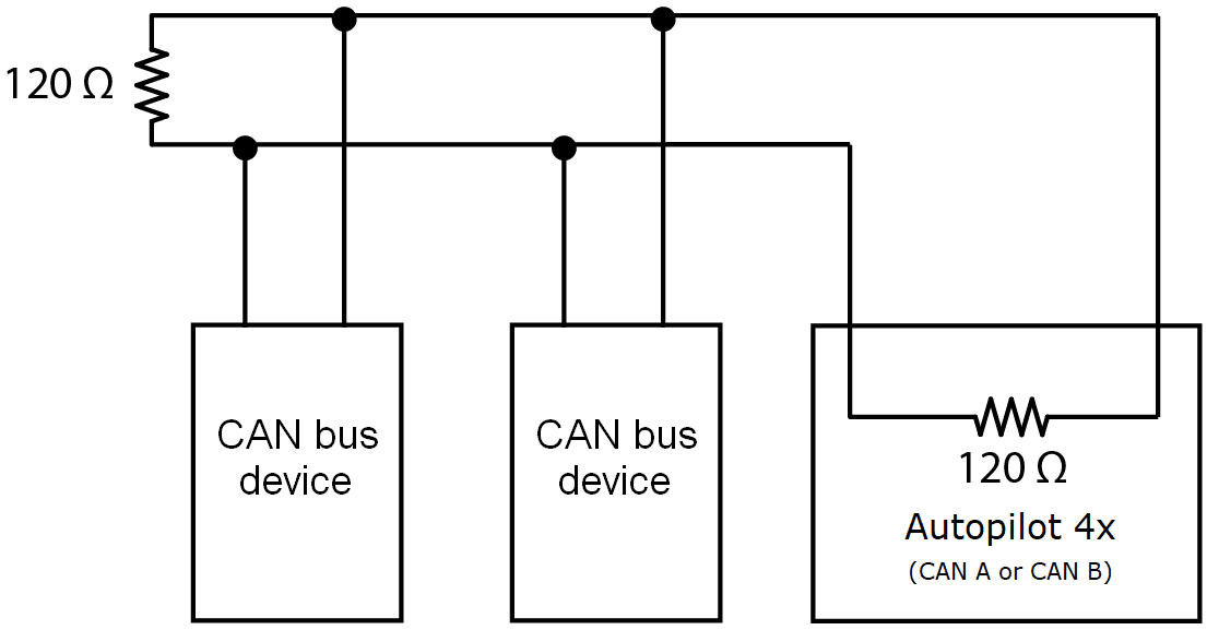
Electrical diagram of CAN bus
Autopilot 4x requires two termination resistors (120 ) to allow multiple CAN Bus devices to be connected to the same line.
Since there is already an internal 120 CAN resistor in the Autopilot 4x (connecting the line to CAN A or CAN B), it is only necessary to place an external 120 resistor at the end of the cable:
© 2026 Embention. All rights reserved.