GNSS Receivers
NexNav GNSS
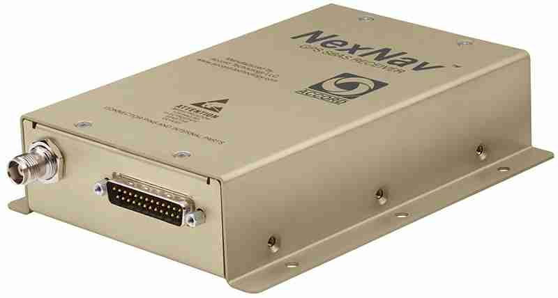
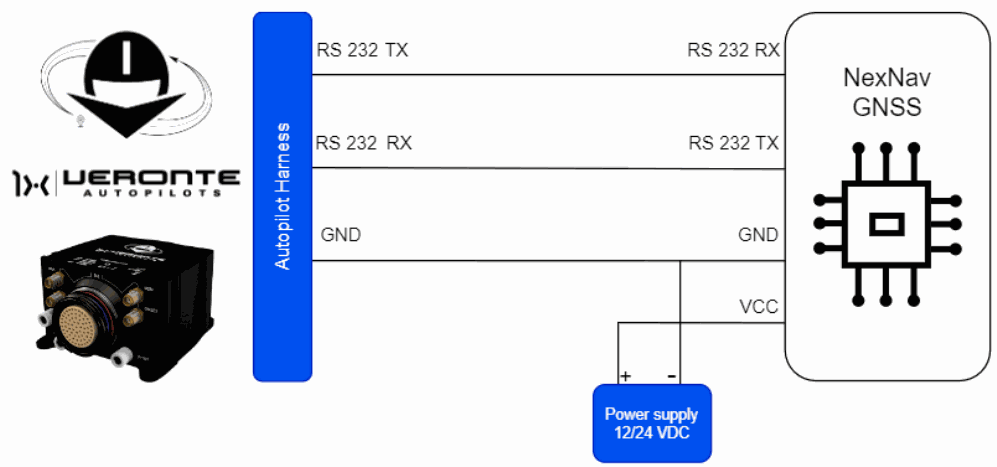
NexNav GNSS sensor integrates with Autopilot 1x via RS232 connection.
Important
Note that it must be connected to an external power supply, sharing signal ground with Autopilot 1x.
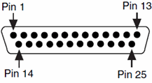
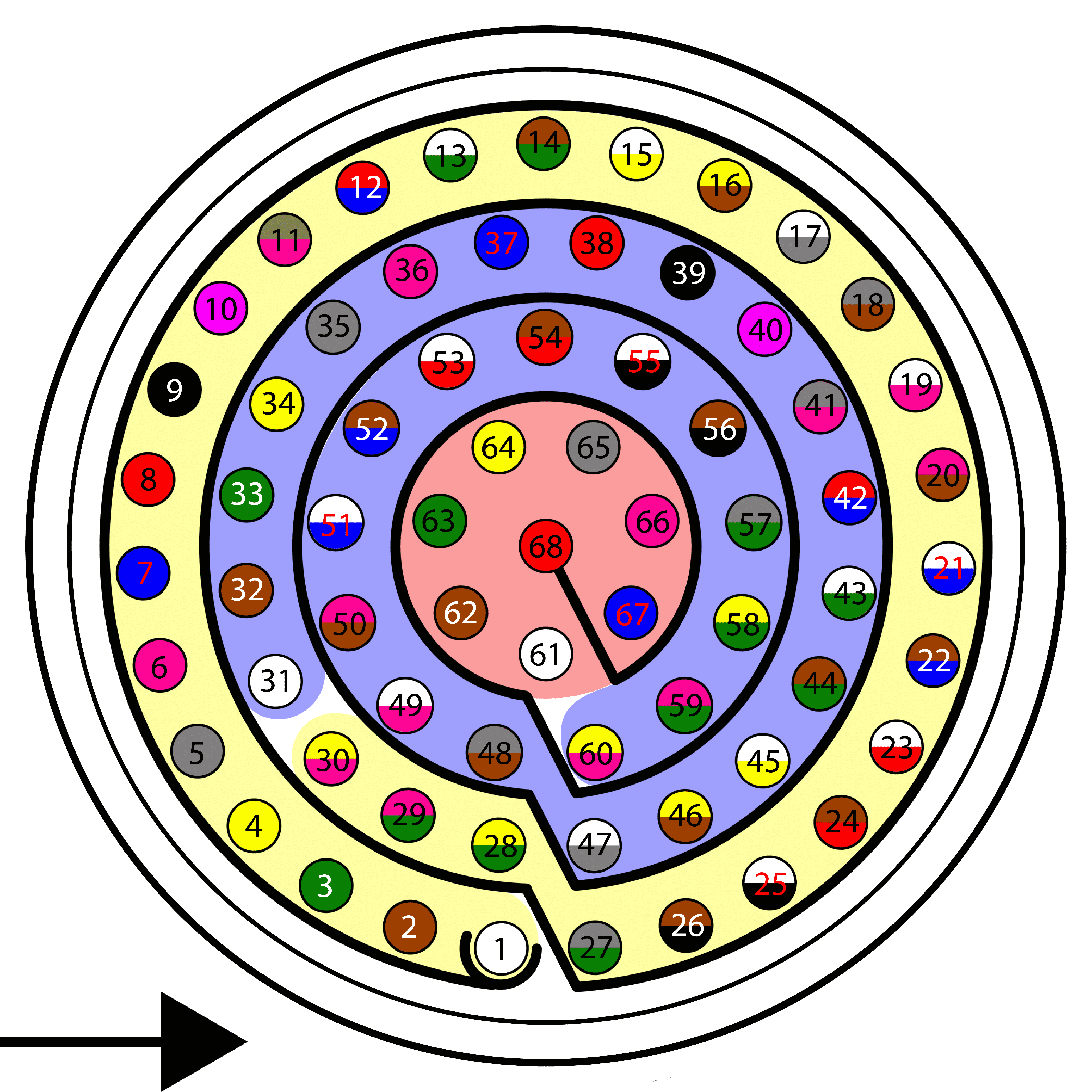
| Autopilot 1x Harness | NexNav GNSS Connector | |||
|---|---|---|---|---|
| PIN | Signal | Color Code | PIN | Signal |
| 19 | RS232 TX | White-Pink | 20 | RS-232 RX, Port 1 |
| 20 | RS232 RX | Pink-Brown | 7 | RS-232 TX, Port 1 |
| 21 | GND | White-Blue | 10 | RS-232 Ground |
Note
For more information about these pins, refer to the Pinout - Hardware Installation section of the present manual.
Warning
Remember!! In Autopilot 1x, all GND pins are common. Note that pin 54 is not a common GND pin.
The software installation of this device with Autopilot 1x is explained in the NexNav GNSS - Integration examples section of the 1x PDI Builder user manual.
Septentrio Mosaic-X5
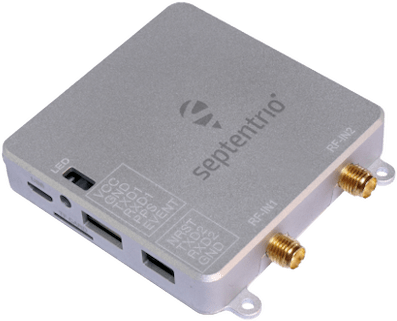
First, Mosaic-X5 must be configured by following the steps detailed in the Mosaic-X5 configuration section.
In addition, the required integration to operate with Veronte Autopilot 1x is described in the Hardware Installation section below.
Mosaic-X5 configuration
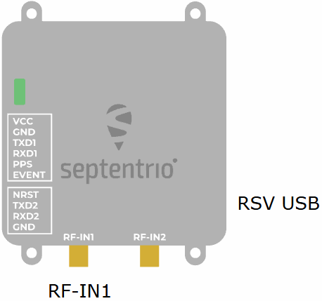
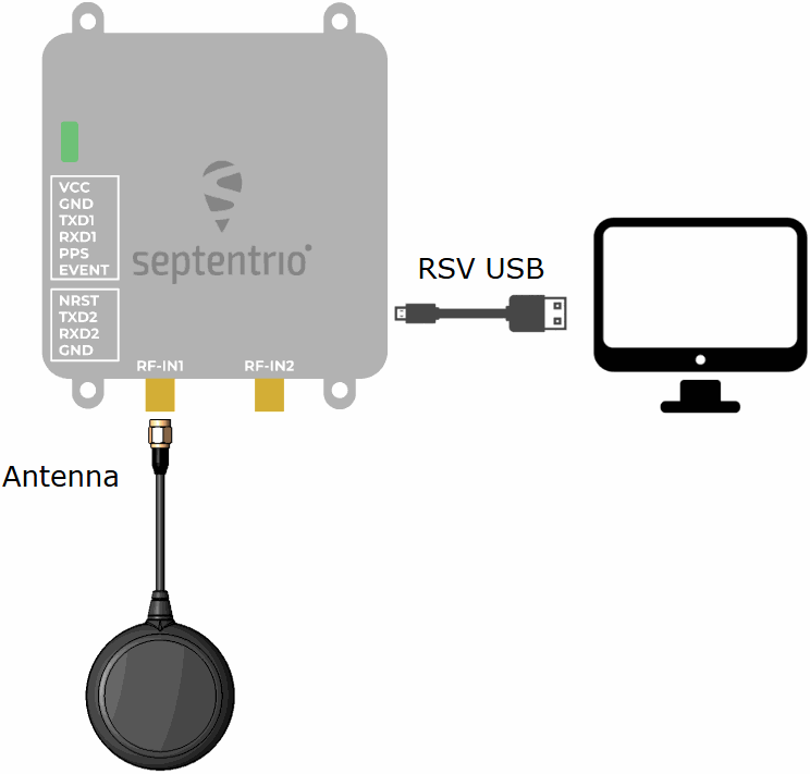
- Connect a main antenna to the RF-IN1 SMA socket.
- Connect the receiver to the computer via USB.
- The receiver will be powered over USB and the LED turns red.
The connection should look like this:
Then, there are two ways to configure Septentrio Mosaic-X5:
- Offical aplication: Septentrio provides its own application for receiver management and configuration: RX Tools.
-
Web interface: The receiver can also be configured by accessing the following IP address in a web browser:
- Access IP address: http://192.168.3.1/
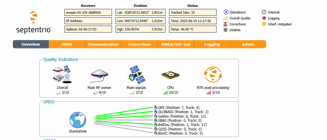
Septentrio Mosaic-X5 - Browser Configuration
Users must follow the configuration steps listed below:
Note
These configuration steps apply when users configure the Mosaic-X5 via web interface.
- Access the web interface using the IP address.
-
Configure the data output through the COM1 port.
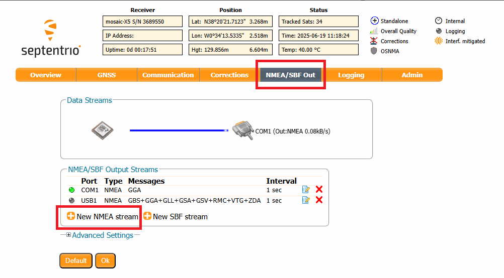
Septentrio Mosaic-X5 - NMEA/SBF Out configuration -
Select the GGA output format.
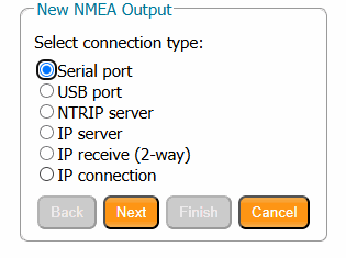
Septentrio Mosaic-X5 - NMEA connection type 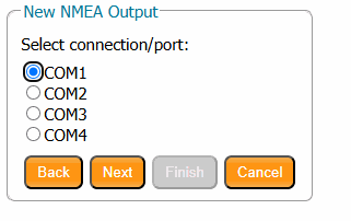
Septentrio Mosaic-X5 - NMEA port -
Set the output frequency to 200 milliseconds.
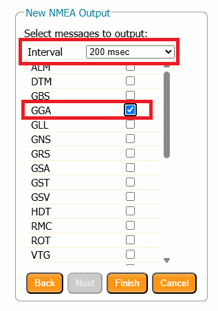
Septentrio Mosaic-X5 - NMEA messages configuration -
Click OK to update the configuration.
-
Save this configuration to the device boot so that it persists after restarts.
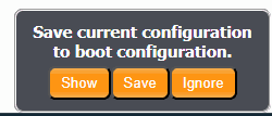
Septentrio Mosaic-X5 - Save configuration
Hardware Installation
Septentrio Mosaic-X5 sensor integrates with Autopilot 1x via RS232 connection.
Important
Since the Mosaic-X5 serial interface operates at TTL levels. A TTL-to-RS232 converter is required between the receiver and Autopilot 1x.
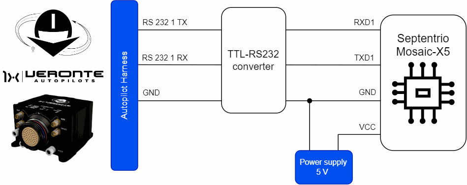
Important
Note that it must be connected to an external power supply, sharing signal ground with Autopilot 1x.
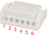
| Autopilot 1x Harness | TTL-232 Conversor | Septentrio Mosaic-X5 Connector (JST) | ||||
|---|---|---|---|---|---|---|
| PIN | Signal | Color Code | Signal | PIN | Signal | Color Code |
| 19 | RS232 TX | White-Pink | RX | 4 | RXD1 | Green |
| 20 | RS232 RX | Pink-Brown | TX | 3 | TXD1 | Blue |
| 21 | GND | White-Blue | GND | 2 | GND | Yellow |
Note
For more information about these pins, refer to the Pinout - Hardware Installation section of the present manual.
Warning
Remember!! In Autopilot 1x, all GND pins are common. Note that pin 54 is not a common GND pin.
The software installation of this device with Autopilot 1x is explained in the Septentrio Mosaic-X5 - Integration examples section of the 1x PDI Builder user manual.
© 2026 Embention. All rights reserved.