Veronte products
CEX/MEX
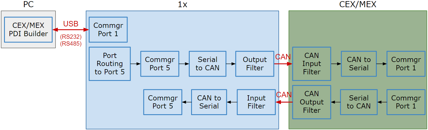
As it is sometimes not possible to connect a CEX/MEX directly to the PC in order to configure it (access CEX/MEX PDI Builder), the Veronte Autopilot 1x is connected to the computer and a connection is made between CEX/MEX and Veronte Autopilot 1x via CAN.
To be able to communicate with CEX/MEX via CAN, the following connection is necessary:
Note
- 1x usually has this configuration by default, but check it out.
- As the steps to be performed in CEX PDI Builder and MEX PDI Builder are exactly the same, only the steps for one of them will be detailed. The interface may differ slightly, but the configuration is the same.
First, connect the CEX/MEX to the Autopilot 1x via CAN. Detailed information on this connection can be found in the:
- CEX connection - Integration examples section of the 1x Hardware Manual.
- MEX connection - Integration examples section of the 1x Hardware Manual.
Then, follow the steps below to make this configuration:
1x PDI Builder side
-
Go to Input/Output menu I/O Setup panel.
Check the connection between the computer and the 1x (usually via RS232 or RS485 are also possible).
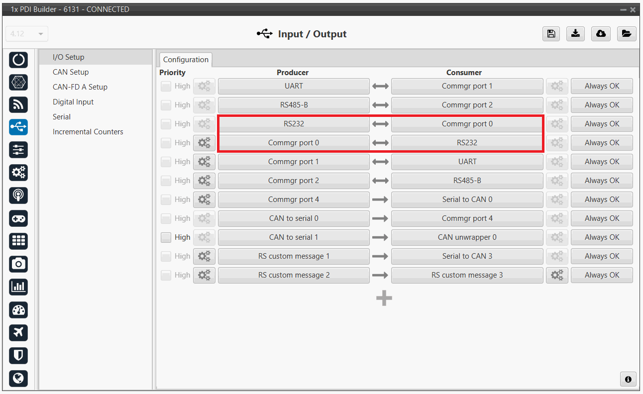
1x PDI Builder - I/O Setup configuration -
Go to Communications menu Ports panel.
Remove Port 5 from the Forward group and add Port 5 to the Route group, with target CEX's Address:
Address = 44000 + Serial number.
The CEX address must be in the range 45000 - 49999.
Note
-
For MEX, the address should look like this:
- Address = 42000 + Serial number.
- The MEX address must be in the range 43000 - 43999.
-
If the theorical address does not work, 999 (unknown) can be used as sometimes the address has not been set in CEX/MEX.
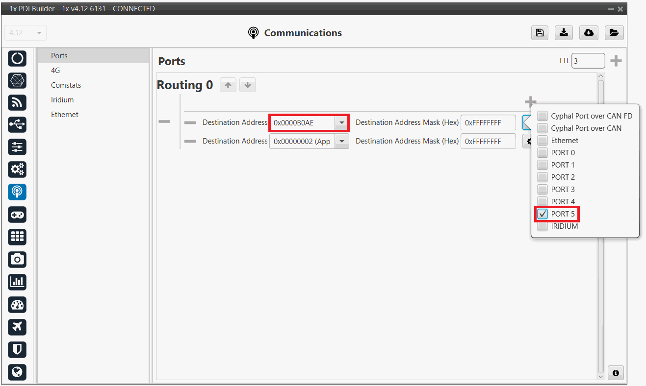
1x PDI Builder - Routing configuration -
-
Go to Input/Output menu I/O Setup panel.
Connect Commgr port 5 to Serial to CAN 1 consumer:
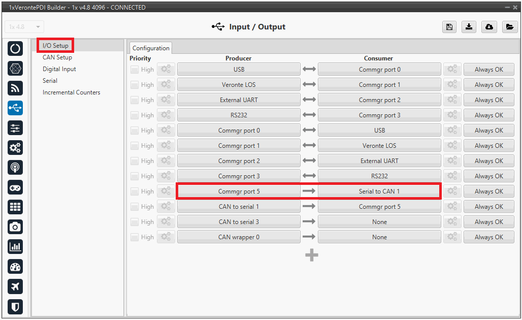
1x PDI Builder - I/O Setup configuration: Serial to CAN Then, connect CAN to serial 1 to Commgr port 5:
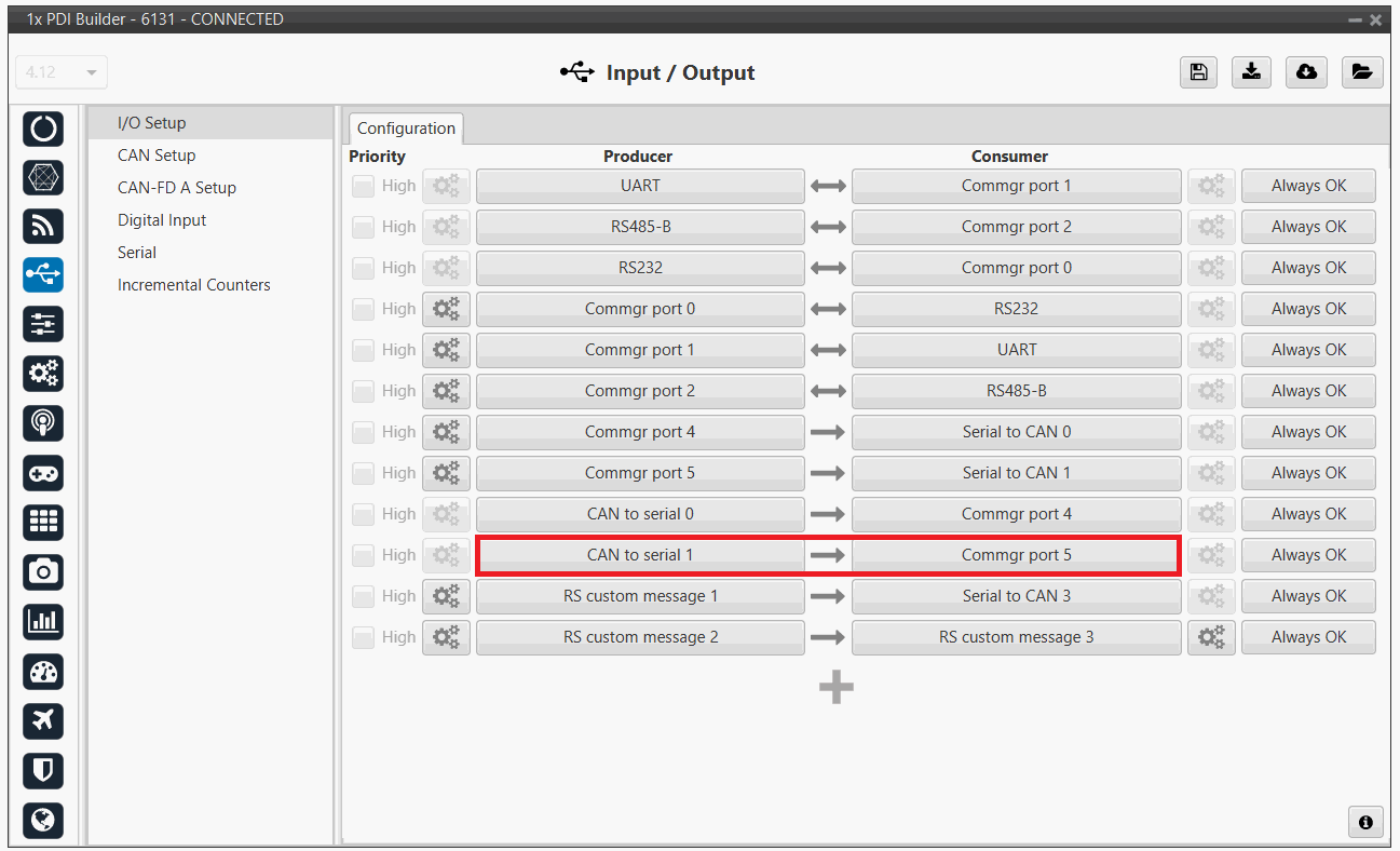
1x PDI Builder - I/O Setup configuration: CAN to serial -
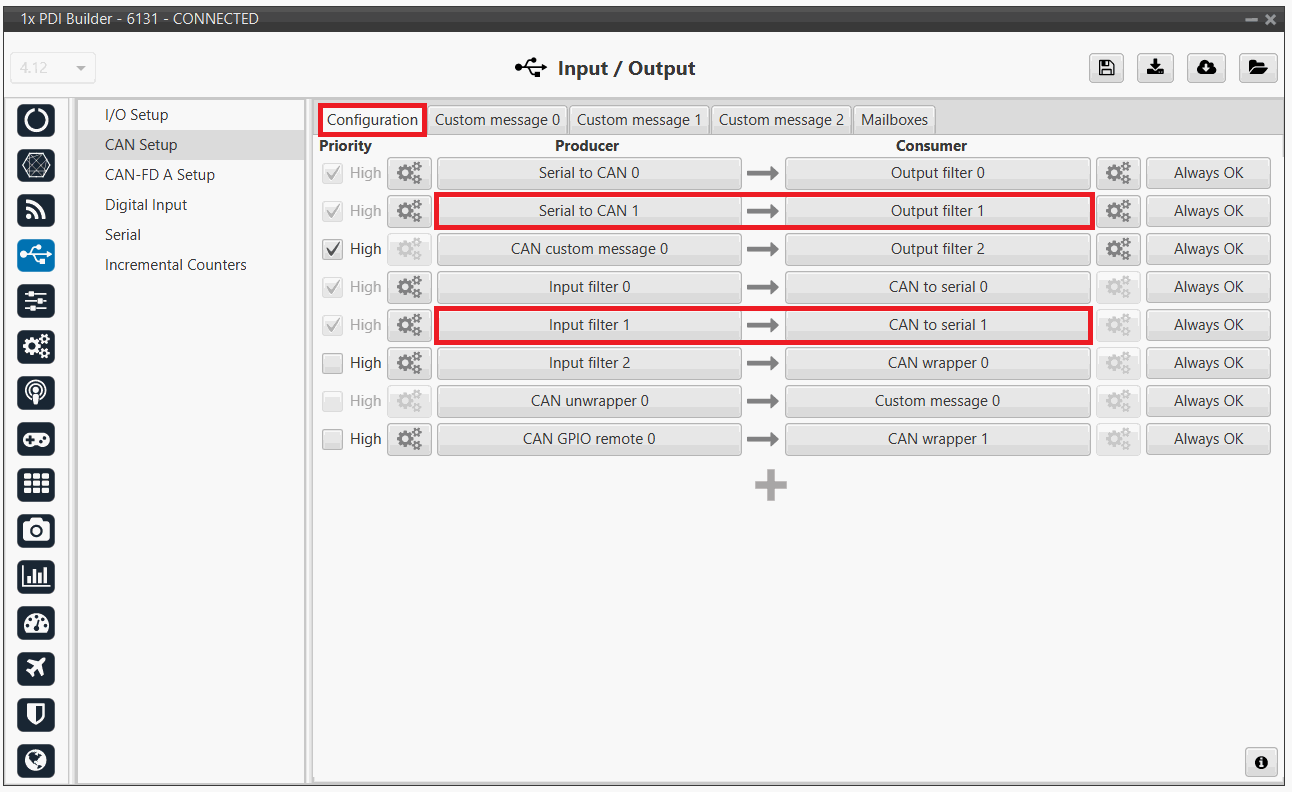
Go to Input/Output menu CAN Setup panel Configuration tab.
Connect a Serial to CAN with the right Id (CAN ID 1302) to an Output filter.
In addition, connect an Input filter with the right Id (CAN ID 1301) to a CAN to serial:
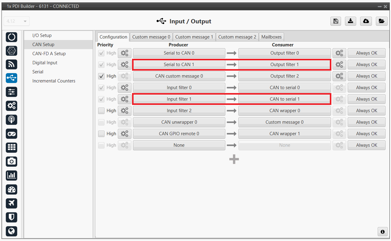
1x PDI Builder - CAN Setup configuration 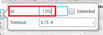
1x PDI Builder - Serial to CAN configuration 
1x PDI Builder - Input filter configuration -
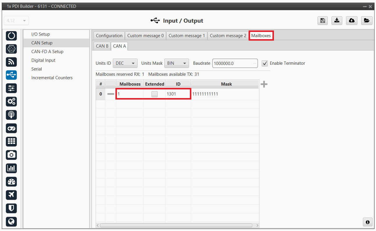
Go to Input/Output menu CAN Setup panel Mailboxes tab.
Finally, configure the reception mailbox with ID 1301, assign at least 4 mailboxes:

1x PDI Builder - Mailboxes configuration
CEX PDI Builder side
Note
This part is already built for CEX default configuration, but the user can check it.
-
Go to Input/Output menu CAN I/O panel Configuration tab.
Connect a CAN Input Filter with the right CAN Address (CAN ID 1302) to CAN to Serial 0.
In addition, connect Serial to CAN 0 with the right CAN Address (CAN ID 1301) to a CAN Output Filter port:
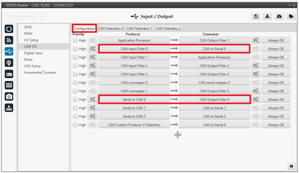
CEX PDI Builder - CAN I/O configuration 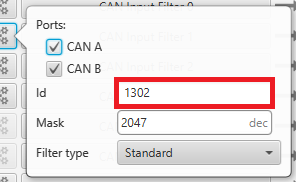
CEX PDI Builder - CAN Input Filter configuration 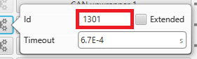
CEX PDI Builder - Serial to CAN configuration -
Go to Input/Output menu I/O Setup panel.
Connect CAN to Serial 0 to any Commgr port, in this case Commgr port 0 is used.
In addition, connect Commgr port 0 to Serial to CAN 0 consumer:
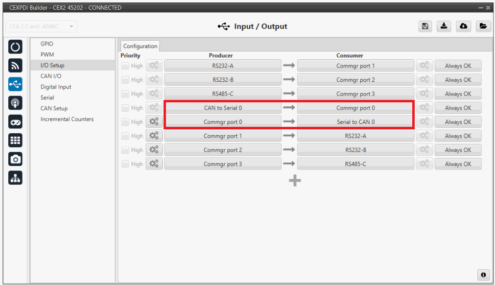
CEX PDI Builder - I/O Setup configuration -
Go to Input/Output menu CAN Setup panel.
Finally, configure the reception mailbox with ID 1302, assign at least 4 mailboxes:
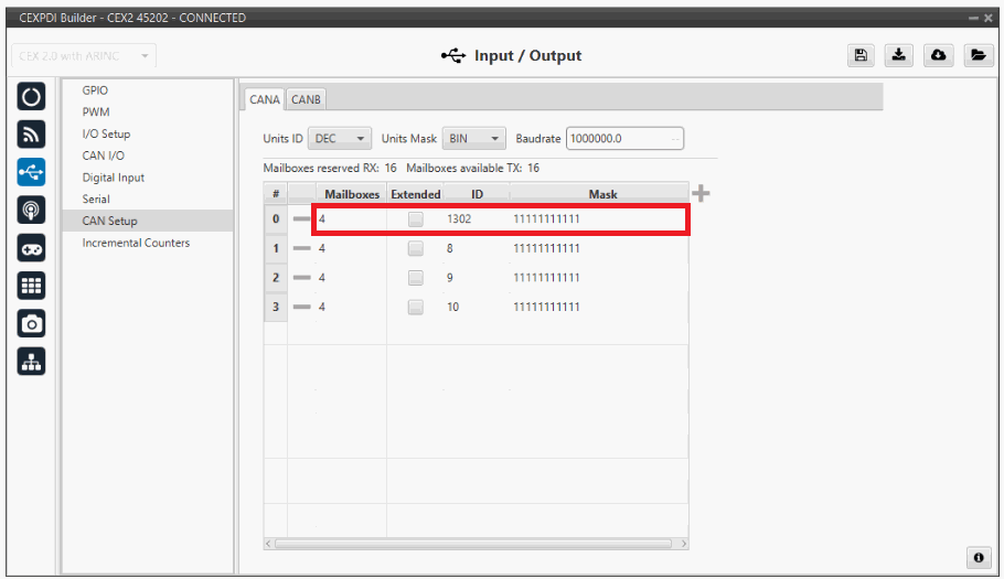
CEX PDI Builder - CAN Setup (Mailboxes) configuration
DRx
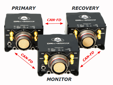
DRx is a redundant system composed of three complete Veronte 1x autopilots. Each autopilot is individually configurable and they communicate with each other via CAN-FD.
The DRx architecture consists of three units serving the following roles:
-
Primary Unit: The default command unit. It acts as the lead controller during standard operations.
-
Recovery Unit: The backup (failover) unit. It assumes command instantly if the Primary unit fails or exceeds defined error thresholds.
-
Monitor: The system supervisor. It does not pilot the vehicle; instead, it executes the arbitration algorithm to assign command to the most suitable unit.
Unit Identification
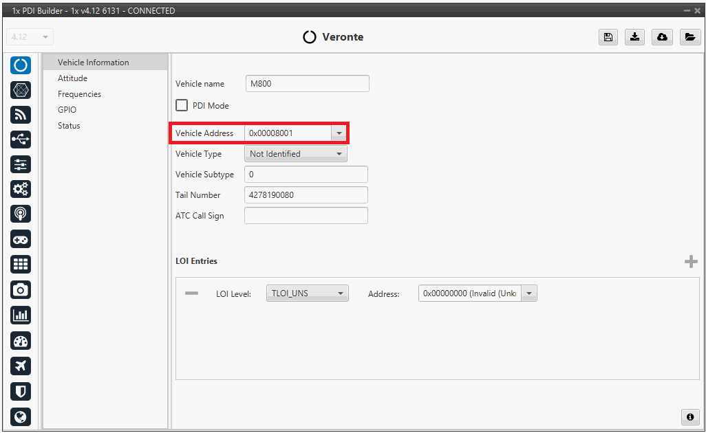
The DRx system utilizes a specific address configuration. The entire system requires a dynamic address, which is assumed by the unit currently in command. Additionally, each hardware unit must be assigned a unique physical address to allow for individual targeting.
Note
The table below provides an example of the address allocation for each unit:
| Unit | Address |
|---|---|
| DRx | 0x8000 |
| Primary Unit | 0x8001 |
| Recovery Unit | 0x8002 |
| Monitor Unit | 0x8003 |
- Go to Veronte → Vehicle information. Assign the respective physical address to each hardware unit. In this example, the Primary unit's address configuration is shown.
- Go to Control → Redundancy setup.
- Set the DRx cluster address in the Arbiter address field.
- Enable the redundancy feature.
- Input the corresponding unit addresses.
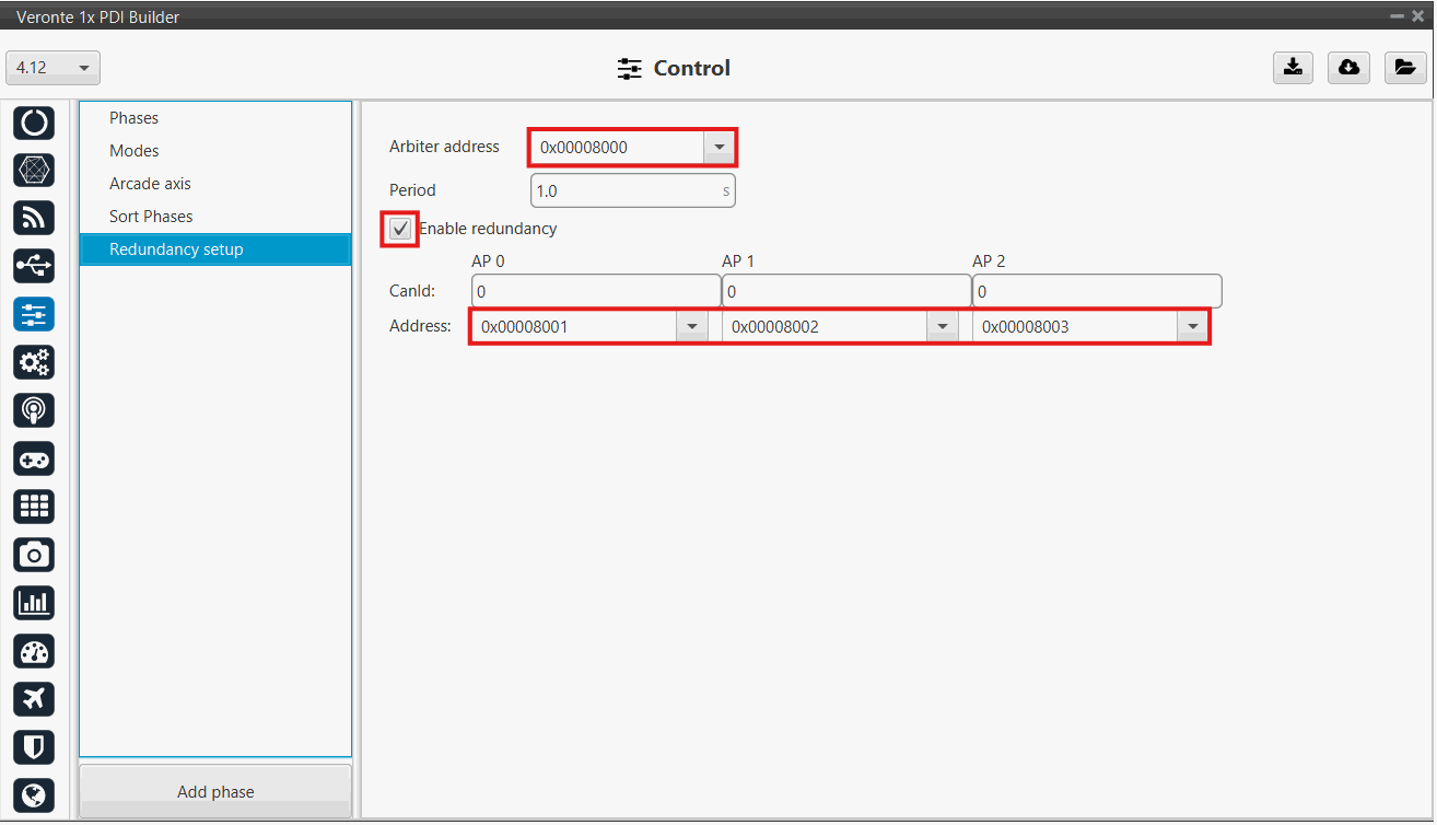
Warning
Assign a non-zero value to the Period field to avoid triggering a PDI Error.
I/O Configuration
Communication Messages
The following I/O configuration enables the correct communication across the three units that compose the DRx system, retransmitting commands to ensure full synchronization among all units.
The communication messages must be configured separately for each unit, assigning a unique ID to every communication pathway. The diagram and table below provide a configuration example illustrating the specific ID assignments for each DRx unit:
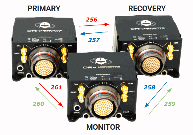
| TX \ RX | Primary | Recovery | Monitor |
|---|---|---|---|
| Primary | - | 256 | 261 |
| Recovery | 257 | - | 258 |
| Monitor | 260 | 259 | - |
Communication IDs between DRx units
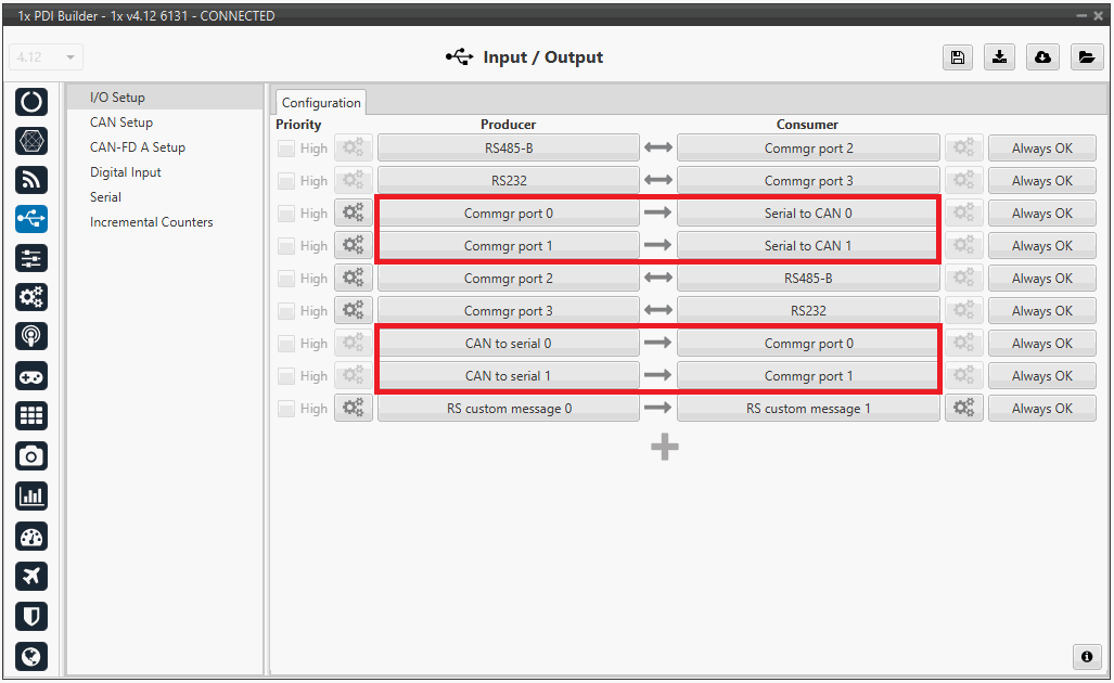
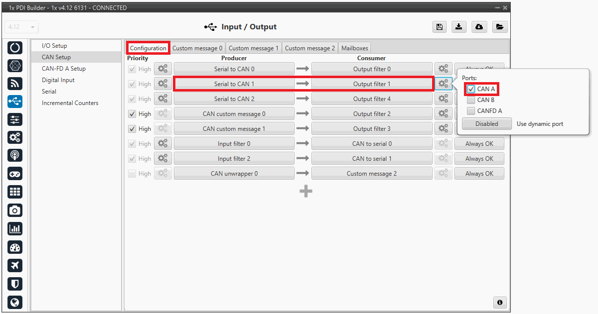
- Go to Input/Output → I/O Setup → Configuration and configure the following parameters to enable the Serial-to-CAN communication between units.
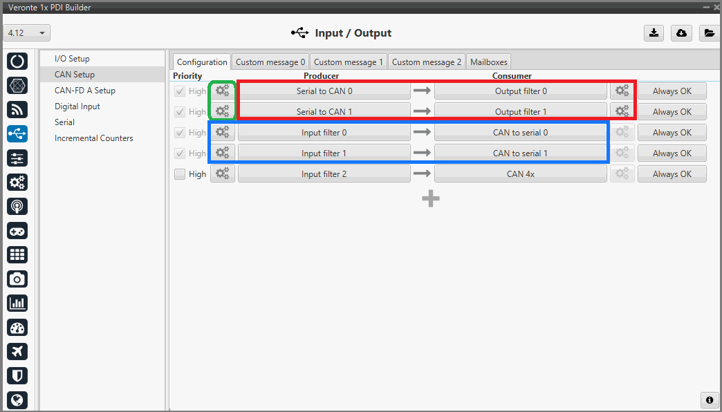
- Go to Input/Output → CAN Setup → Configuration tab.
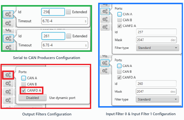
- To send commands from this autopilot, connect 2 Serial to CAN producers to 2 Output filter consumers, both configured for CAN-FD A. In this case Output filter 0 and Output filter 1 are selected.
- To receive commands from the other two units, connect 2 Input Filter producers to 2 CAN to Serial consumers. In this case, Input filter 0 and Input filter 2 are selected.
Therefore, to ensure seamless communication between units, you must correctly configure the IDs of both Serial to CAN producers, as well as the ID and mask in the Input Filters.
Arbitration Messages
The Monitor must inform both the Primary and Recovery units of the current command status by transmitting the Arbitration message.
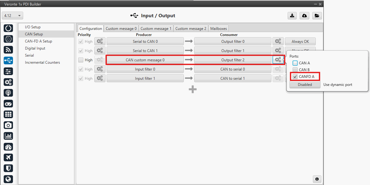
- In the Monitor Configuration: Go to Input/Output → CAN Setup → Configuration tab.
- To transmit the Arbitration message, connect a CAN Custom message producer to an Output filter consumer, also configured for CAN-FD A. In this case CAN Custom message 0 and Output filter 2 are selected.
-
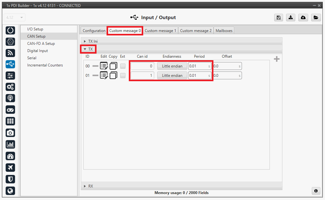
Go to Input/Output → CAN Setup → Custom message 0 → TX and select the
 icon to add a field.
- Enter the corresponding CAN ID of the Arbitration message. In this example 127.
- Select the Little Endian mode.
- Enter the corresponding period and offset. In this example, a period of 0.01s and no offset have been set.
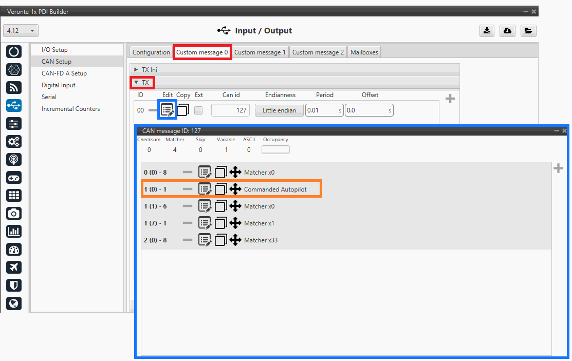
Arbitration Message Configuration Important
The Arbitration message follows a predefined structure:
Byte Position Value Description 0 0 - 7 0x00 Header 1 0 0x00 / 0x01 CAP (Commanded Autopilot) 1 1 - 6 0x00 Hardcoded 1 7 0x01 Hardcoded 2 0 - 7 0x33 Hardcoded The Commanded Autopilot is the boolean final output (User bit) of the Arbitration algorithm:
- If the variable is FALSE: Primary unit is in command.
- If the variable is TRUE: Recovery unit is in command. Additionally, the Primary and Recovery units must be configured to accept and interpret the arbitration message.
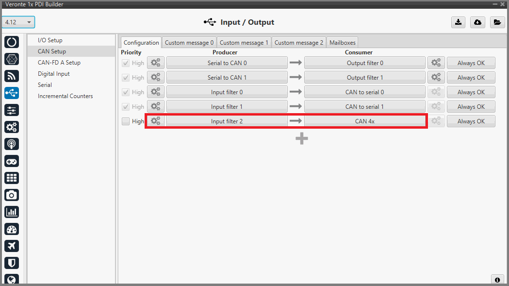
-
In the Primary/Recovery Configuration: Go to Input/Output → CAN Setup → Configuration tab
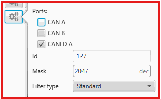
- Connect an Input filter producer to the predefined CAN 4x consumer, in this case Input filter 2 is selected.
- In the Producer settings, enable reception of arbitration message. In this example, ID 127 is selected.
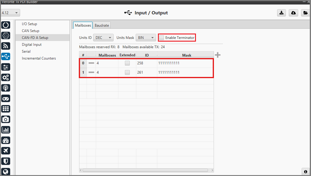
- In the Primary/Recovery Configuration: Go to Input/Output → CAN-FD A Setup → Mailboxes tab.
- Configure the CAN-FD mailboxes to accept the incoming messages defined. According to this example (Primary unit), the corresponding IDs are 257 (Data from Recovery unit), 260 (Data from Monitor unit) and 127 (Arbitration message).
- Enable the internal CAN-FD Terminator.
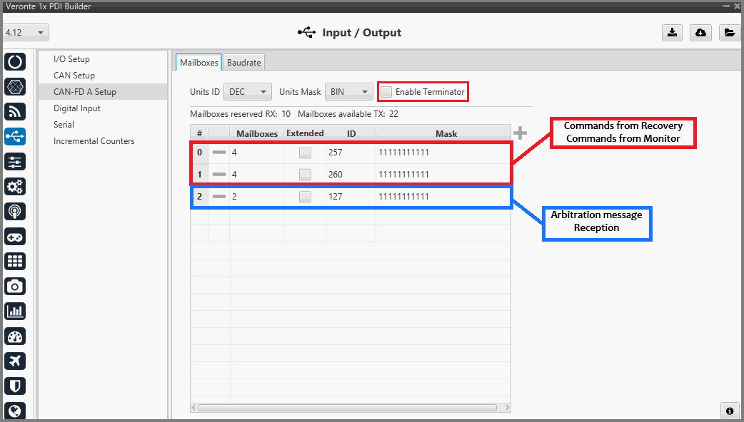
Note
In the Monitor configuration, only 2 Mailboxes need to be configured. The mailbox for the Arbitration message is not required. In this example (Monitor unit), the corresponding IDs are 261 (Data from Primary unit) and 258 (Data from Recovery unit). Enabling the internal CAN-FD Terminator is required to ensure proper bus operation.
Communication Configuration
Routing
Configure the system to route messages to the CAN interfaces based on the target Unit Address, i.e. tell the system exactly which physical port to use when sending a message to a specific Unit Address (whether the message comes from Ground or is generated internally).
-
CASE 1: Primary/Recovery Configurations
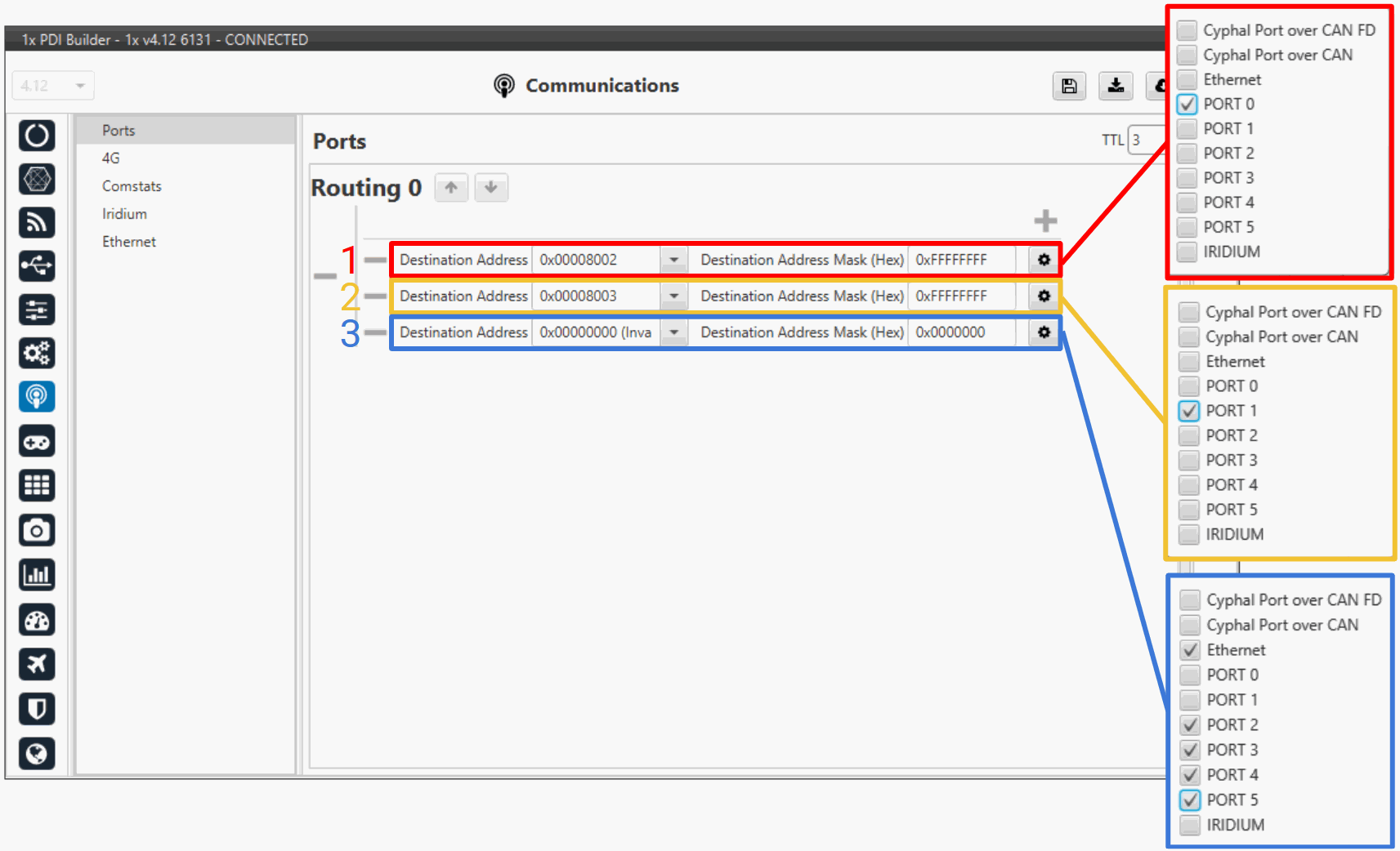
Ports - Primary/Recovery Configuration -
Route 1 (red): Establishes the communication port between the Primary and Recovery units.
-
Route 2 (yellow): Establishes the communication port between the Primary and Monitor units.
-
Route 3 (blue): Establishes communication port between the Primary and other system components.
Note
Symmetric Address Configuration
The image above illustrates the configuration from the Primary unit's perspective (where the route targets the Recovery address, e.g.,
0x00008002). When configuring the Recovery unit, the port layout and logic remain identical, but you must invert the target address to point to the Primary unit instead (e.g., changing0x00008002to0x00008001). -
-
CASE 2: Monitor Configuration
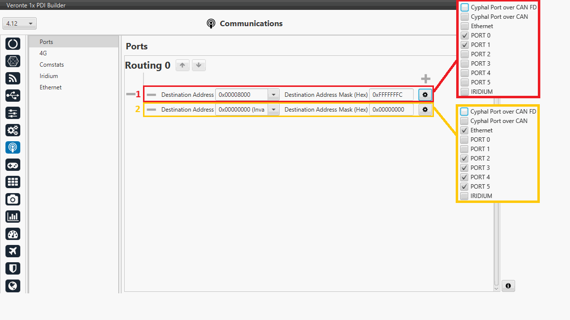
Ports - Monitor Configuration - Route 1 (red): Establishes the communication port between the Monitor and the Primary and Recovery units.
- Route 2 (yellow): Establishes the communication port between the Monitor and other system components.
Ethernet
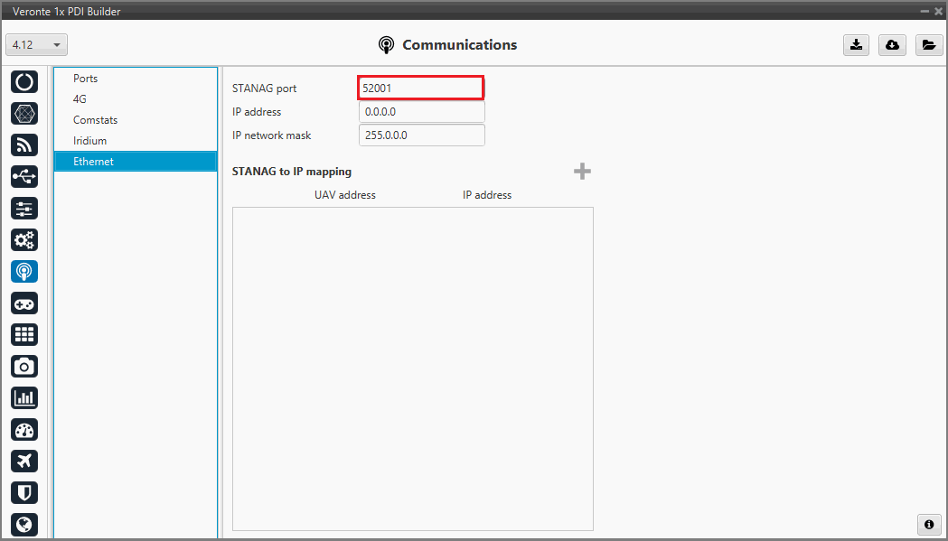
It is recommended to modify the port addresses of the hardware units to optimize Ethernet performance. The following table outlines the specific port assignments used in this example:
| Unit | Port |
|---|---|
| Primary | 52001 |
| Recovery | 52002 |
| Monitor | 52003 |
| Default (Maintenance Mode) | 52000 |
- Go to Communications → Ethernet and and assign a unique port to each unit to prevent bottlenecks. The example below illustrates the configuration for the Primary unit:
- FIREWALL CONFIGURATION: Users must enable the new UDP ports (In the example 52001, 52002 and 52003) in the firewall to ensure the correct operation of the three Autopilot 1x Ethernet connection. This configuration might need to be performed by the cybersecurity manager of your company.
Important
Veronte Link must be configured to detect all three operational ports simultaneously. For further information, please refer to the UDP Multicast Configuration - Operation section of the Veronte Link user manual.

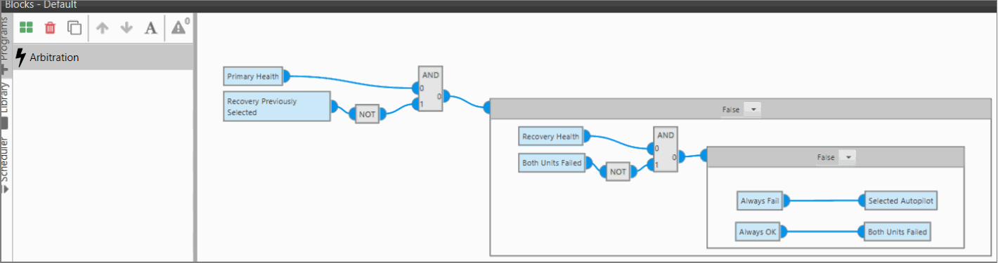
Monitor Arbitration Logic
The Arbitration Logic implemented in the Monitor unit is the core decision-making process of the DRx system. It is responsible for evaluating the operational integrity of the flight controllers and managing the transition of command. The boolean output of this logic is the 'Commanded Autopilot' variable included in the Arbitration message.
-
Implementation: Configured via Block Programs in the PDI.
-
Flexibility: The user defines the criteria for a "Healthy" vs. "Failed" unit.
- Binary Approach: Simple Pass/Fail flags (e.g., "If IMU Status is failed -> Unit unhealthy -> Switch").
- Score-Based Approach: Weighted average of multiple variables.
-
Data Inputs: The Monitor receives health flags and sensor data from Primary and Recovery via custom messages in CANFD.
An example is provided in the image below. Access the Core 2 - Blocks menu to perform the configuration.
Units Synchronization
Automations
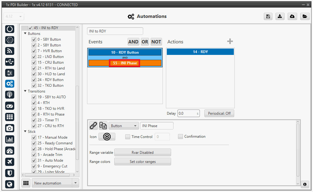
To guarantee that a Phase Change command triggers the exact same state across all three units simultaneously. For example, if an event is assigned ID 55 on the Primary unit, it must share that same ID on both the Recovery and Monitor units.
Ensure that every major system event (e.g., Phase changes, Flight Mode switches) has an identical ID across all three configurations.
Hint
Keep Event IDs Synchronized Across Units
When one of the units has unique automations, use Dummy Events to prevent ID mismatch across the rest of the cluster.
For example:
- Scenario: The Primary unit has complex automations that the Monitor or Recovery units do not need.
- Problem: These extra events consume IDs, potentially offsetting the numbering for subsequent shared events.
-
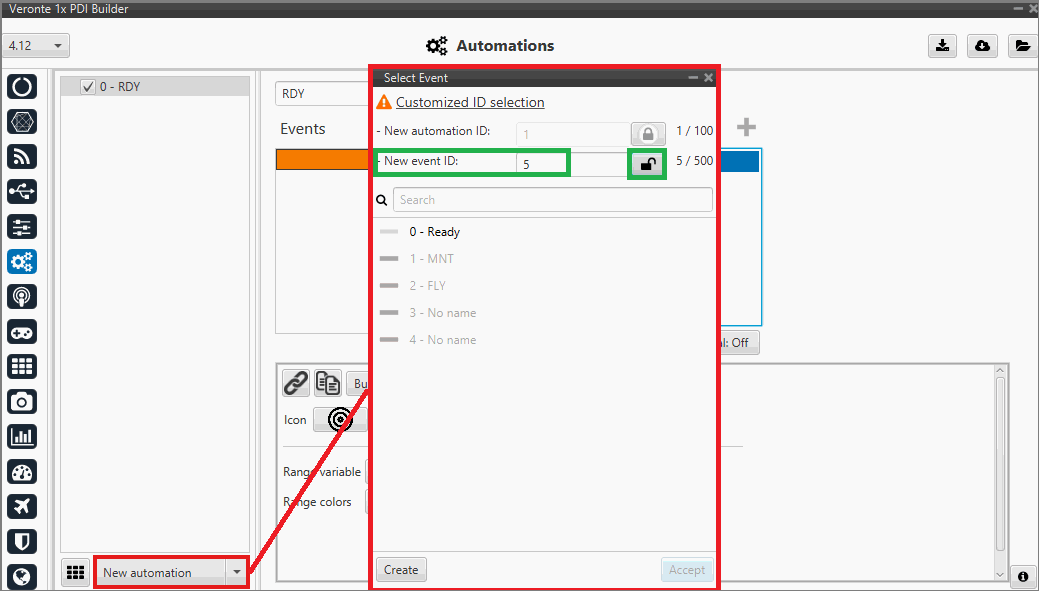
Solution: Create "Dummy Events" on the Recovery/Monitor units:
- Create a new event.
- Assign it the exact same ID as the Primary's unique event.
- Leave the action completely empty.
-
Go to Automation → New Automation and press and hold the lock button until it unlocks. You can then assign the matching IDs to the dummy events across the DRx units.
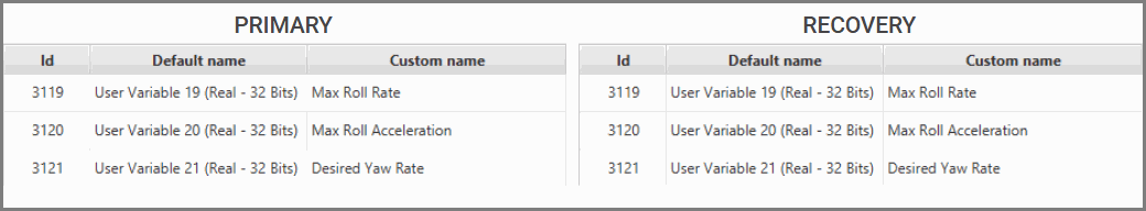
User Variables
Ensure that shared commands modify the same parameter in every unit.
- Go to UI → Variables and ensure that the same variables are configured with the identical ID across all units.
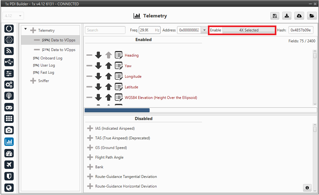
Telemetry
To ensure that only the Active Unit transmits data to the Ground Control Station (Veronte Ops), locate the Enable bit field for the telemetry stream and map it to the 4x Selected internal bit. In the present example (Primary unit configuration):
- If 4x Selected == 1 (TRUE): Telemetry is Enabled. Primary unit talks to the ground.
- If 4x Selected == 0 (FALSE): Telemetry is Disabled. Recovery unit talks to the ground.
Pilot Input
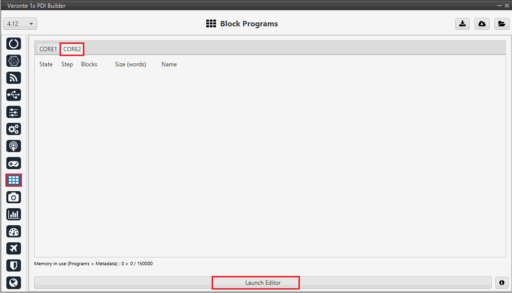
If a stick program is required, ensure that Pilot Commands sent to the Shared DRx System Address are accepted by all three hardware units. The system requires configuring all three units to listen for commands from the shared address:
- Go to Block Programs → CORE 2 → Launch Editor:
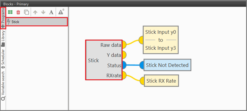
- Create a Stick program and add the Stick block. For further information, please review the Stick block.
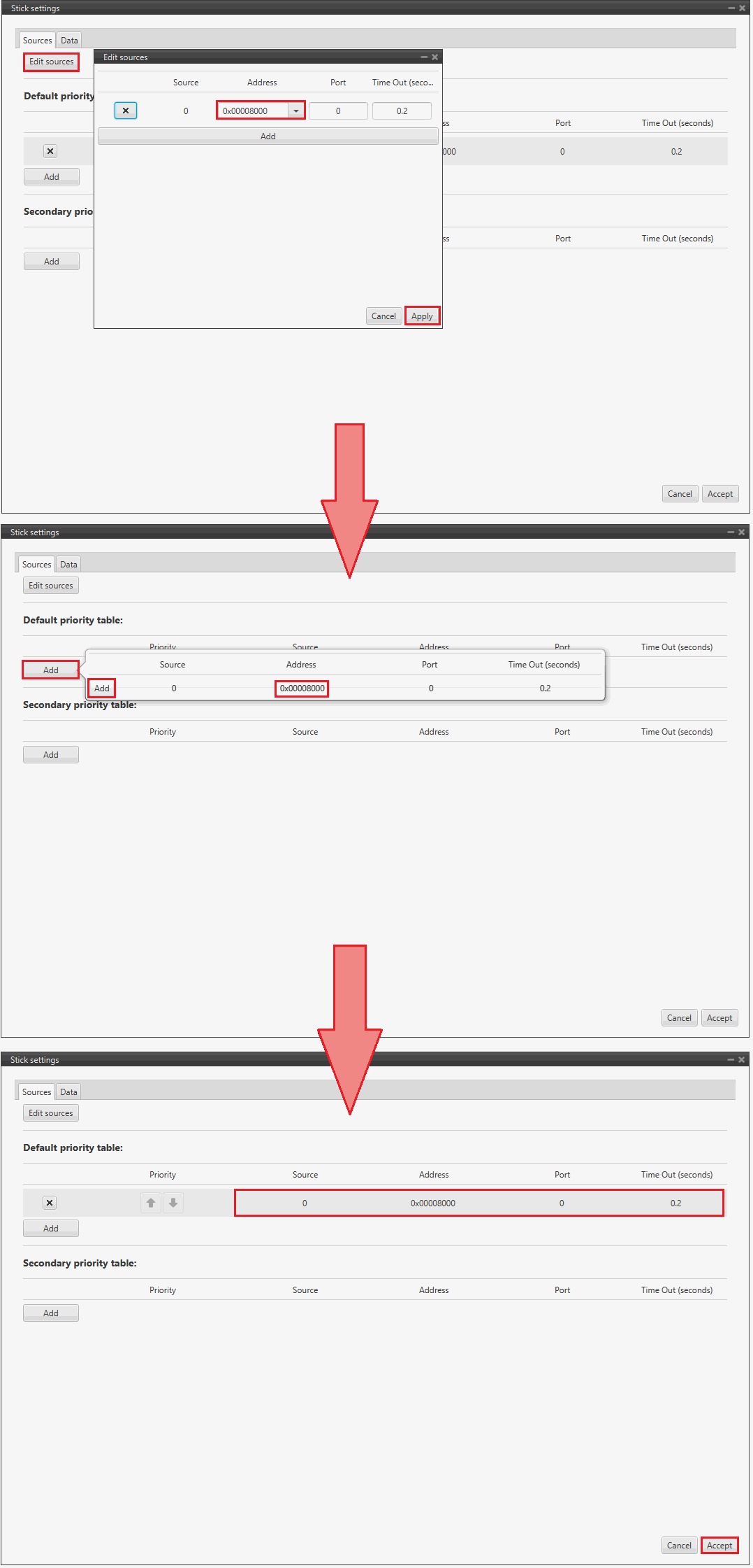
- Open Stick block properties by double-clicking on the stick block.
- Navigate and Edit sources tab.
- Add a new source using the DRx ID. In this example, the Id is 0x8000.
MC01
In order to communicate a Veronte Autopilot 1x with a MC01 via CAN, the following connection is required:
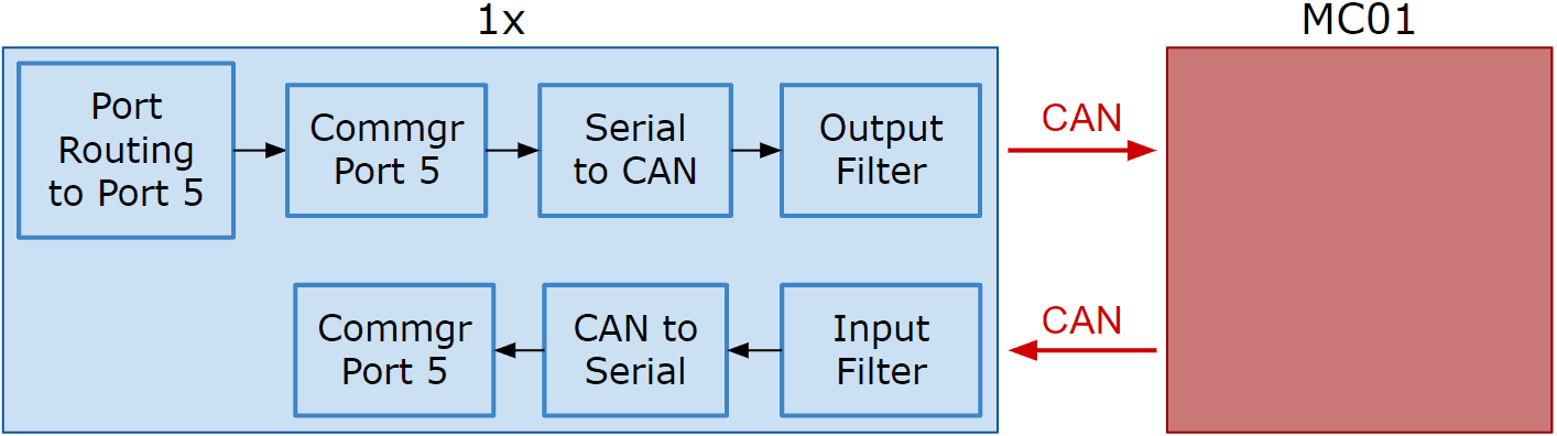
First, connect the MC01 to the Autopilot 1x via CAN. Detailed information on this connection can be found in the MC01 connection - Integration examples section of the 1x Hardware Manual.
Then, the following steps explain how to configure the communication between an Autopilot 1x and a MC01.
MC01 PDI Builder side
- By default, MC01 is configured with a connection Serial to CAN, with the following Standard CAN IDs:
- Tx CAN Id: 1301
- Rx CAN Id: 1302
1x PDI Builder side
-
Go to Communications menu Ports panel.
Remove Port 5 from the Forward group and add Port 5 to the Route group, with target MC01's Address. This address must be chosen in the destination path of the MC01 (40117 for the example).
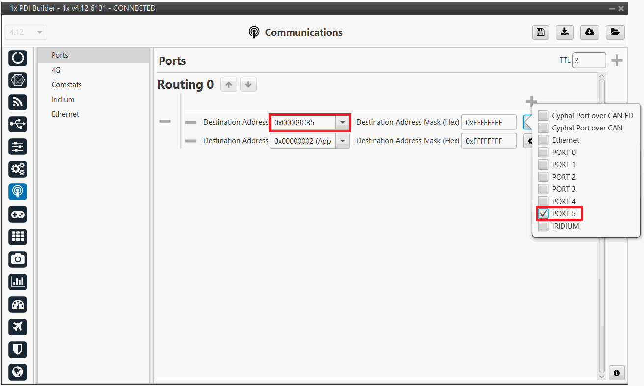
1x PDI Builder - Routing configuration -
Go to Input/Output menu I/O Setup panel.
Connect the Commgr port 5 to the Serial to CAN 1.
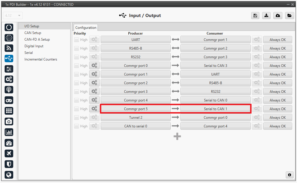
1x PDI Builder - I/O Setup configuration: Serial to CAN Then, connect CAN to serial 1 to Commgr port 5:
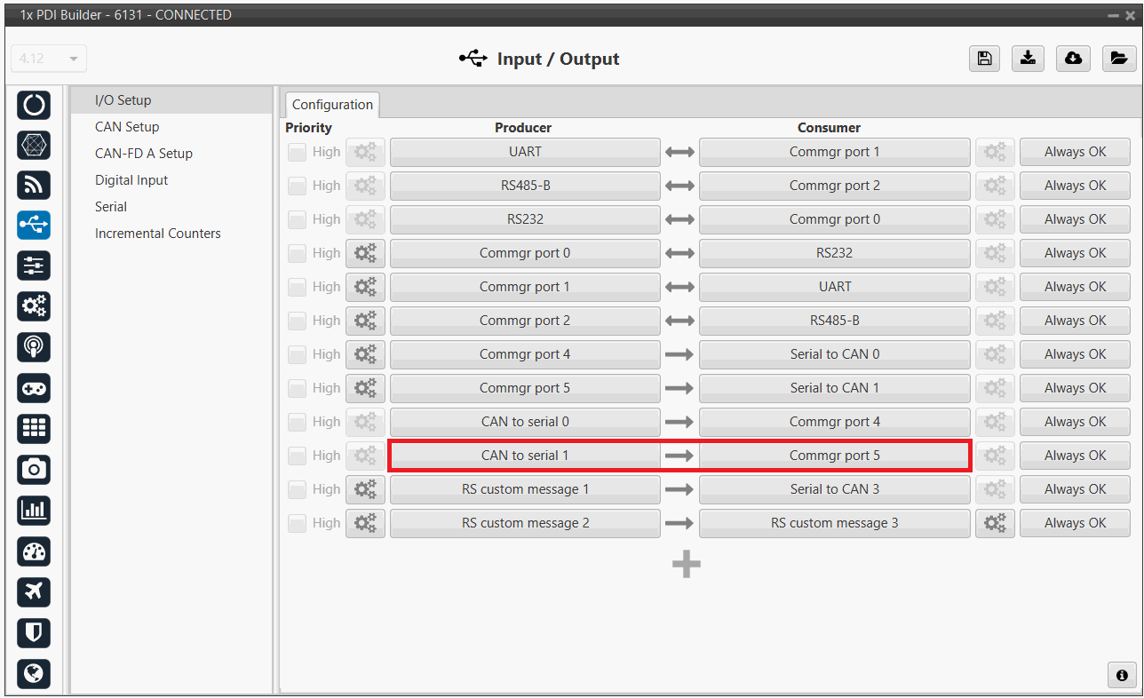
1x PDI Builder - I/O Setup configuration: CAN to serial -
Go to Input/Output menu CAN Setup panel Configuration tab.
Connect a Serial to CAN with the right Id (CAN ID 1302) to an Output filter.
In addition, connect an Input filter with the right Id (CAN ID 1301) to a CAN to serial:
1x PDI Builder - CAN Setup configuration 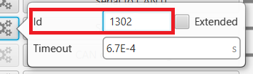
1x PDI Builder - Serial to CAN configuration 
1x PDI Builder - Input filter configuration -
Go to Input/Output menu CAN Setup panel Mailboxes tab.
Finally, configure the reception mailbox with ID 1301, assign at least 1 mailbox:
1x PDI Builder - Mailboxes configuration
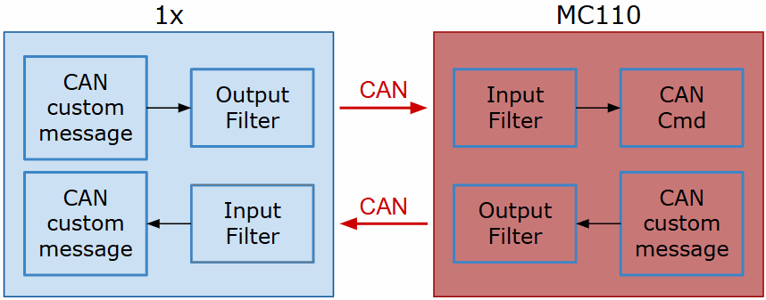
MC110
In order to send commands from a Veronte Autopilot 1x to a MC110 via CAN and vice versa, the following connection is required:
Warning
If users have the Autopilot 1x connected to a PC while commanding via CAN to a MC110 unit (e.g. when performing test operations), this connection to the PC must be via RS232/485.
For more information on a connnection via RS232/485 with a Veronte Autopilot 1x, refer to the Wiring connection - Integration examples section of the 1x Hardware Manual.
First, connect the MC110 to the Autopilot 1x via CAN. Detailed information on this connection can be found in the:
- MC110 connection - Integration examples section of the 1x Hardware Manual.
CAN commands from Autopilot 1x to MC110
Follow the steps below to make this configuration:
1x PDI Builder side
-
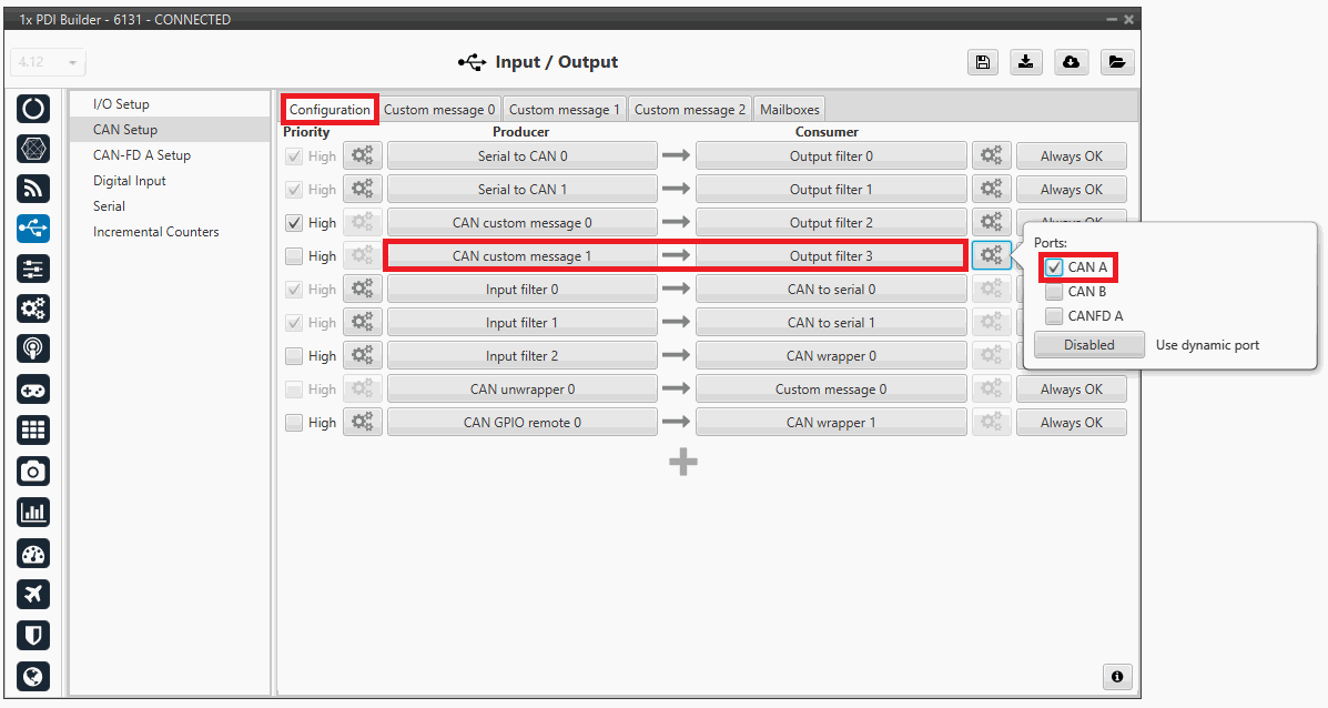
Go to Input/Output menu CAN Setup panel Configuration tab.
Connect a CAN custom message producer (in this case CAN custom message 1 is used) to an Output filter consumer, in this example Output filter 3.
In addition, configure the Output filter with the correct CAN Bus, in this example CAN A has been selected:
1x PDI Builder - CAN Setup configuration -
Go to Input/Output menu CAN Setup panel Custom message 1 tab (since the producer CAN custom message 1 has been connected to the output filter).
-
Add a new message in TX (as it is for tranmission) with CAN ID 1434. More information on the configuration of CAN messages can be found in the TX/TX Ini Messages (Custom Messages) - Input/Output section of this manual.
-
Next, configure the message to be sent with whatever variable users wish to use to command. The variable should be set to compressed signed 32-bit.
Users should send the values from 0 to max_rpm (or from -max_rpm to max_rpm if negative commands are desired to be allowed).
To do this, it is recommended to control the variable internally as a throttle, for this set the Encode from 0 to 1 (or from -1 to 1 for negative speeds).
And for decode it to rpm values, the Decode parameter must be configured from 0 to max_rpm (or from -max_rpm to max_rpm if negative commands are allowed):
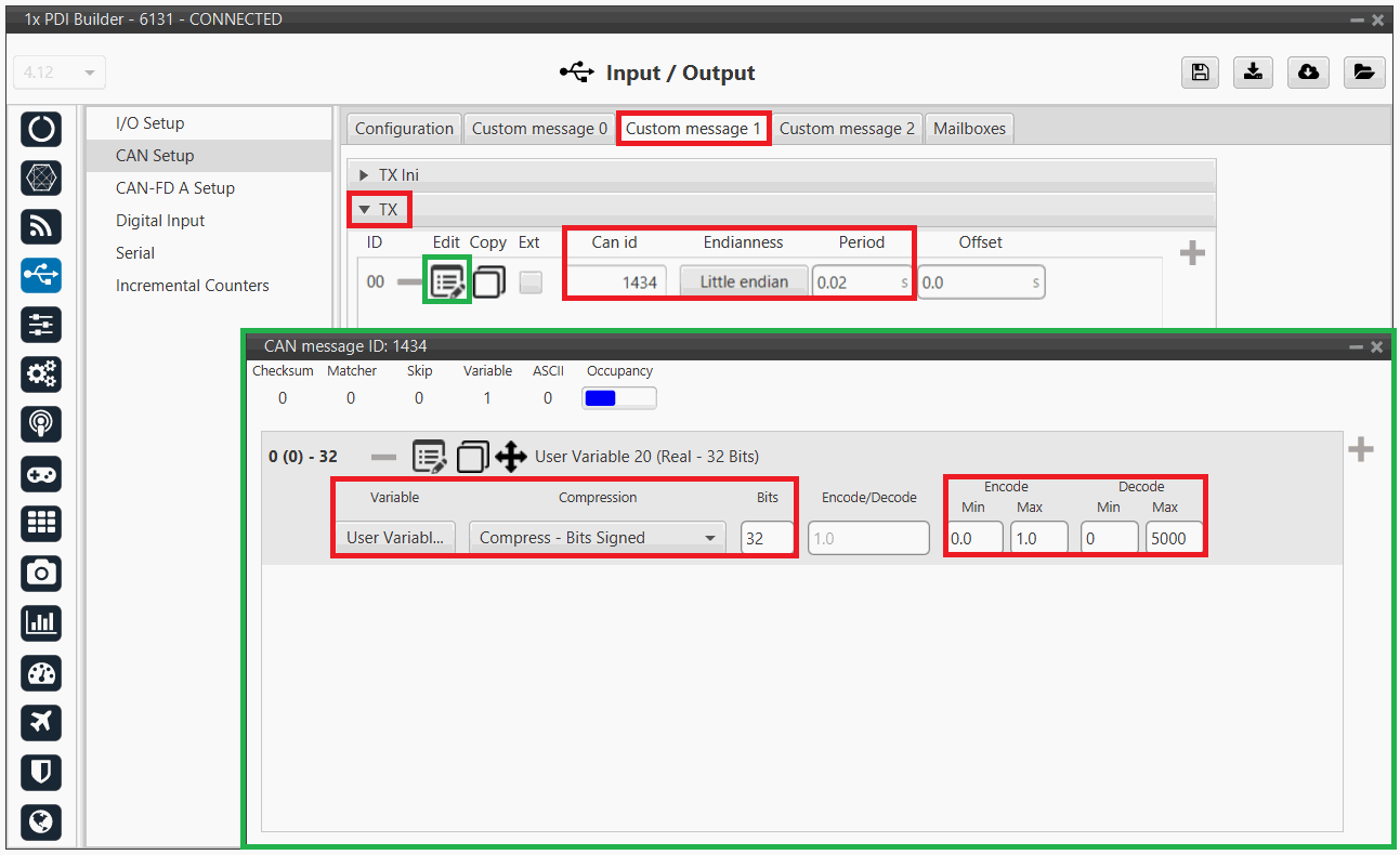
1x PDI Builder - CAN custom message 1 configuration For more information on configuring CAN custom messages, refer to the Custom Messages types - Input/Output section of this manual.
-
Warning
Remember that it is necessary to have at least 1 free mailbox for TX messages.
MC110 PDI Builder side
-
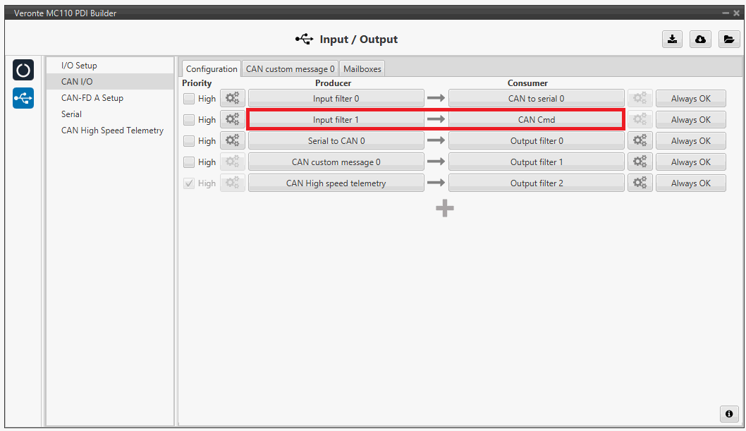
Go to Input/Output menu CAN I/O panel Configuration tab.
Connect an Input filter producer, in this example Input filter 1, to the CAN Cmd consumer.
In addition, configure the input filter with the following parameters:
- Port: CAN B
- CAN Id 1434
- Mask: 2047 dec
- Filter type: Standard
MC110 PDI Builder - CAN I/O configuration 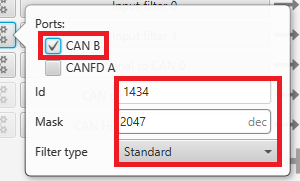
MC110 PDI Builder - Input filter configuration -
Go to Input/Output menu CAN I/O panel Mailboxes tab.
Configure at least 4 reception mailboxes with ID 1434 in the CAN B bus:
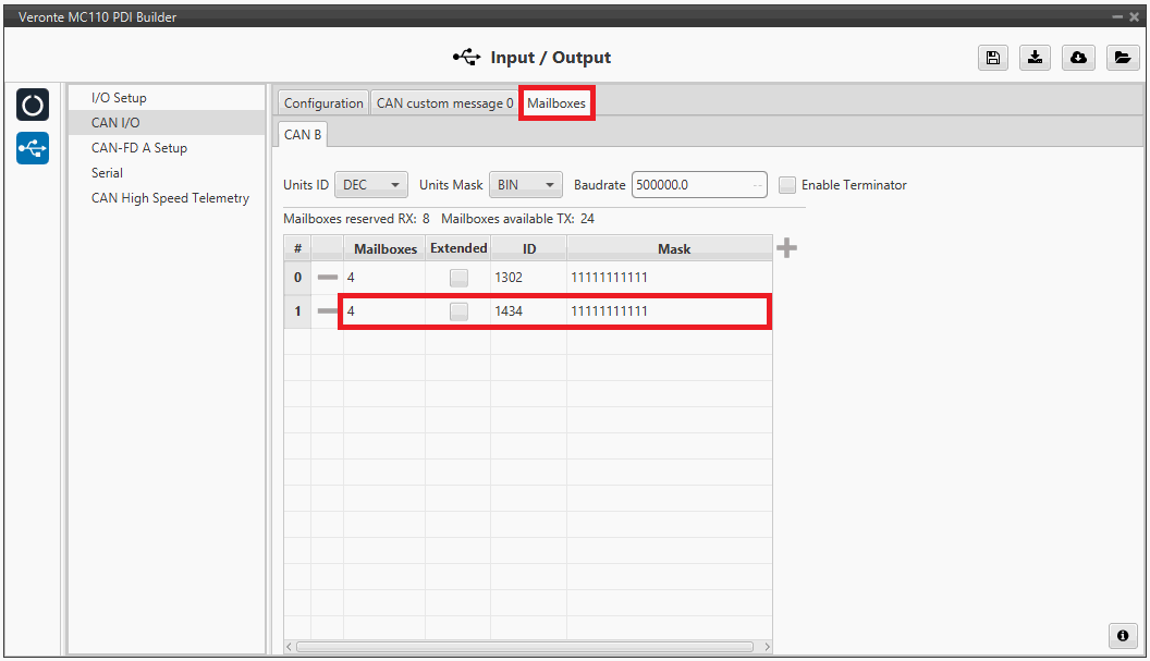
MC110 PDI Builder - Mailboxes configuration -
Go to MC menu FOC Control panel Control Input.
Make sure that m_CAN or m_CAN_PPM mode is selected. For more information on these parameters, refer to the Control Input (FOC Control) - MC section of MC110 PDI Builder user manual.
CAN commands from MC110 to Autopilot 1x
Follow the steps below to make this configuration:
MC110 PDI Builder side
-
Go to Input/Output menu CAN I/O panel Configuration tab.
Connect CAN custom message 0 producer to an Output filter consumer, in this example Output filter 1.
In addition, configure the Output filter with the correct CAN Bus, in this example CAN A has been selected:
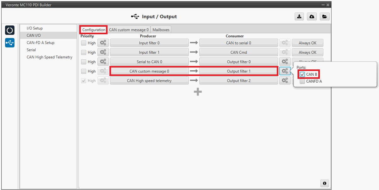
MC110 PDI Builder - CAN I/O configuration -
Go to Input/Output menu CAN I/O panel CAN custom message 0 tab.
Add a new message in TX with the variables the user wishes to send back to Autopilot 1x.
In this example, the message with CAN ID 100 is sending the power input as well as the board temperature as uncompressed variables.
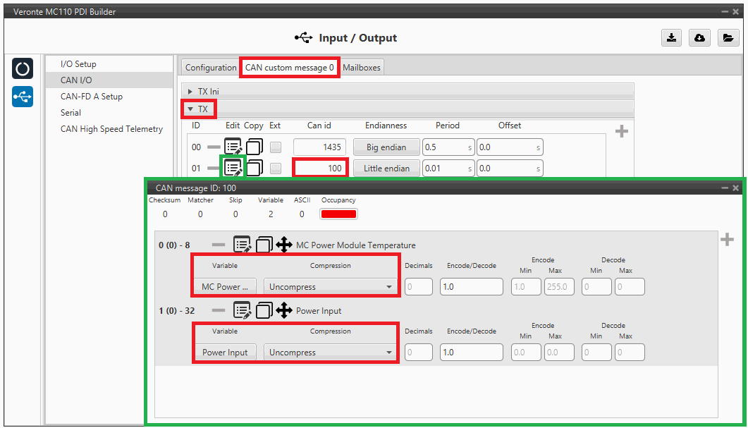
MC110 PDI Builder - CAN custom message 1 configuration For more information on configuring CAN custom messages, refer to the Custom Messages types - Input/Output section of this manual.
Note
If the variables are compressed/encoded on the MC110 side when sent, they must be decompressed/decoded on the Autopilot 1x unit on reception.
1x PDI Builder side
-
Go to Input/Output menu CAN Setup panel Configuration tab.
Connect an Input filter producer (in this case Input filter 3) to a Custom message consumer (Custom message 1 has been selected).

1x PDI Builder - CAN Setup configuration In addition, according to the send message set in the MC110 PDI Builder software, configure the input filter with the following parameters:
- Port: CAN A
- CAN Id 100
- Mask: 1110000 bin
- Filter type: Standard
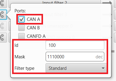
1x PDI Builder - Input filter configuration -
Go to Input/Output menu CAN Setup panel Custom message 1 tab (since the input filter has been connected to the Custom message 1 consumer).
Users can configure the reception of MC110 variables and store them internally for other uses in the configuration.
To do this, add in RX fields the same messages that have been configured in the MC110 PDI Builder as TX Messages:
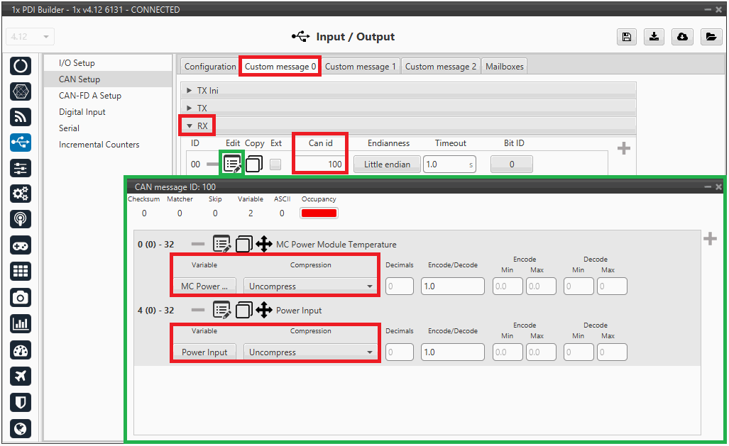
1x PDI Builder - Custom message 1 configuration For more information on configuring CAN custom messages, refer to the Custom Messages types - Input/Output section of this manual.
-
Go to Input/Output menu CAN Setup panel Mailboxes tab.
Finally, configure the reception mailboxes.
In this case, CAN messages with ID 100 and with ID 103 to 109 (8 messages in total) are being sent, which in binary is: 0110 0100 and from 0110 0111 to 0110 1101.
Therefore, 8 mailboxes are configured with ID 01100100 and mask 1110000 in the CAN A bus:
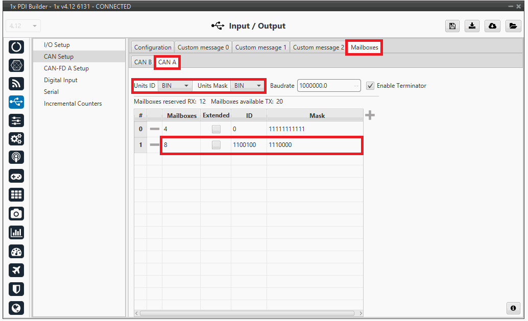
1x PDI Builder - Mailboxes configuration For more information on mailboxes, see the Mailboxes (CAN Setup) - Input/Output section of this manual.
Veronte Gimbal
This section explains the configuration required to control and operate Veronte Gimbal 10z or Veronte Gimbal 30z.
On the one hand, the following diagram illustrates the communication required between a Veronte Autopilot 1x and the Veronte Gimbal to control its movements:
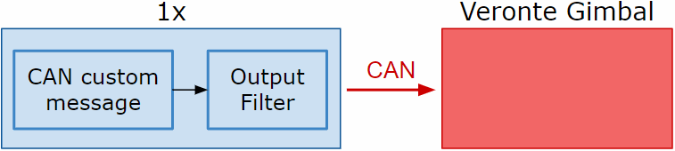
On the other hand, to allow communication between Veronte Autopilot 1x and the video board integrated in the Veronte Gimbal camera the following connection is required:
In the 1x PDI Builder software there is already a template with the required configuration shown in the diagrams above. Users can access it in the following way:
- Open 1x PDI Builder app.
-
Click '1xVeronte' option.
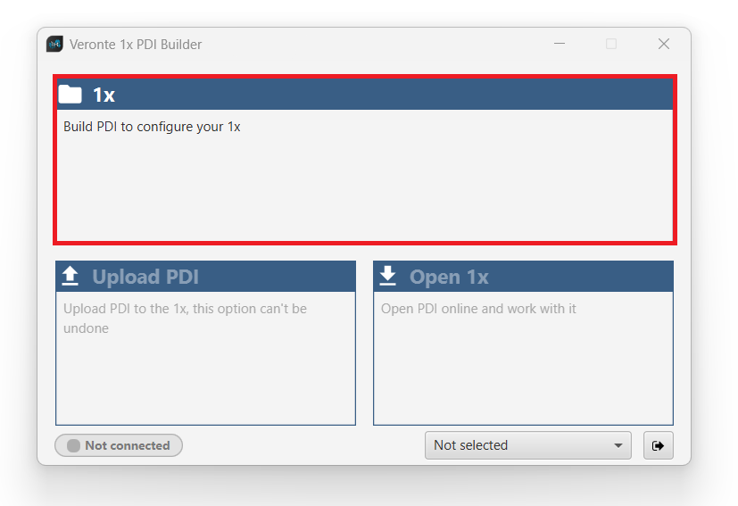
Veronte Gimbal - 1xVeronte option -
In the initial menu of the app, import a configuration from the repo clicking on
 .
.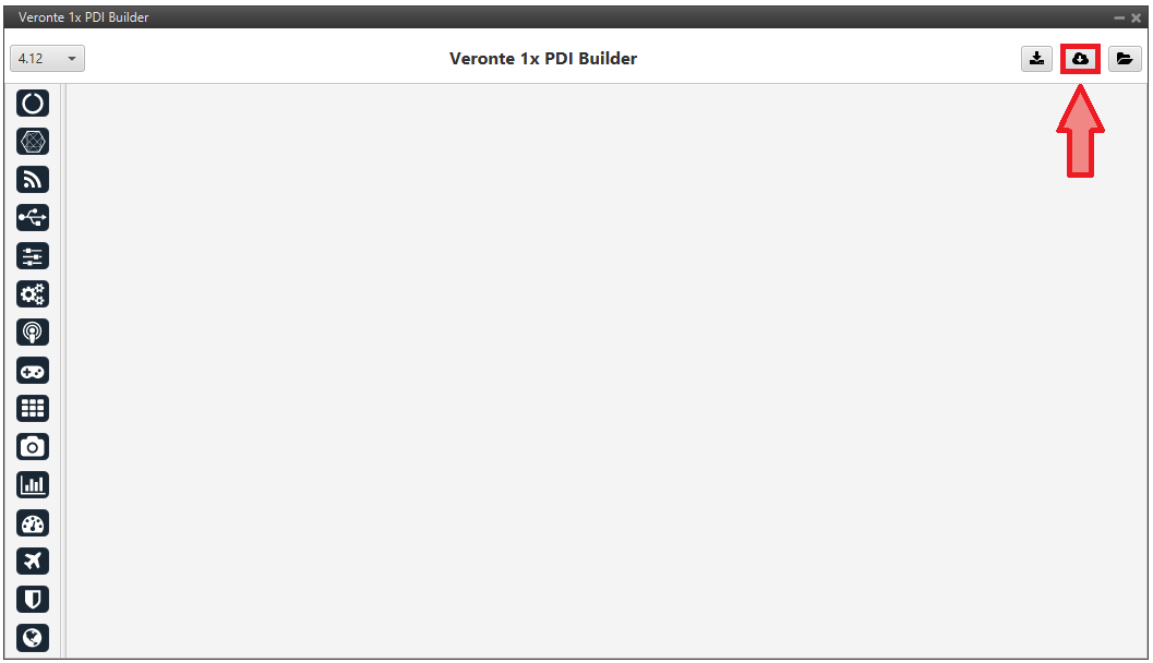
Veronte Gimbal - Import from repo The following window will appear while the templates are being downloaded:
Veronte Gimbal - Downloading templates -
In the templates menu, select the Veronte Gimbal configuration template and press Import to import it to the app.
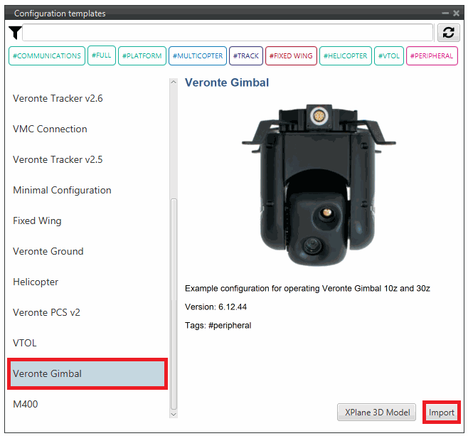
Veronte Gimbal - Veronte Gimbal configuration template
Now, users have to add the Veronte Gimbal control aspects of this configuration template to their own Autopilot 1x configuration.
Controlling Veronte Gimbal movement
Concerning the movement control of the Veronte Gimbal, these are the relevant parts of the configuration:
-
In the Input/Output menu CAN Setup panel Configuration tab.
A CAN custom message producer must be connected to an Output filter consumer. In this example, CAN custom message 0 is connected to Output filter 2 and CAN A bus has been chosen.
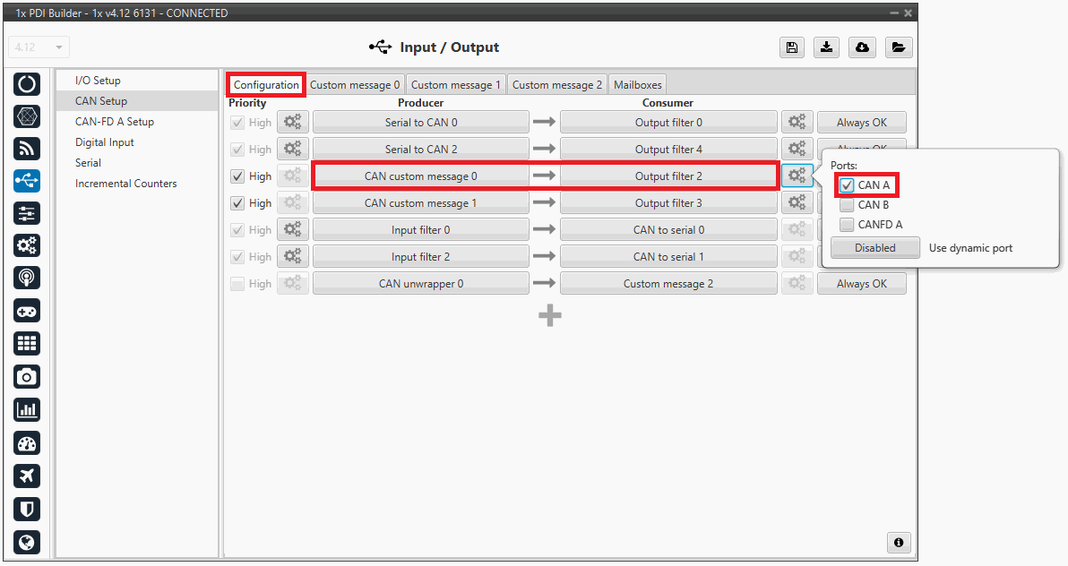
Veronte Gimbal - CAN Setup configuration panel -
In the Input/Output menu CAN Setup panel Custom message 0 tab (since the producer CAN custom message 0 has been connected to the output filter).
The following parameters must be set for 2 CAN messages on TX (as they are for tranmission) with CAN ID 0 and 1. More information on the configuration of CAN messages can be found in the TX/TX Ini Messages (Custom Messages) - Input/Output section of this manual.
Warning
These specific CAN IDs are entered because they have to match the ones configured in the Gimbal, which are configured by default with these ids.
- Can id: 0 / 1
- Endianness: Little endian
- Period: 0.01 s
Veronte Gimbal - Custom message panel Click on
 to access their configuration. This is almost the same for both messages but changing the variable:
Veronte Gimbal - CAN custom message ID 0 configuration -
Matcher
- Value: 3
- Bits: 8
-
Variable
- Variable: Joint 0 of Gimbal 0
- Compression: Compress - Bits Signed
- Bits: 24
- Encode - Min/Max: 0.0/3.1416
- Decode - Min/Max: 0/8388608
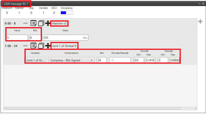
Veronte Gimbal - CAN custom message ID 1 configuration -
Matcher
- Value: 3
- Bits: 8
-
Variable
- Variable: Joint 1 of Gimbal 0
- Compression: Compress - Bits Signed
- Bits: 24
- Encode - Min/Max: 0.0/3.1416
- Decode - Min/Max: 0/8388608
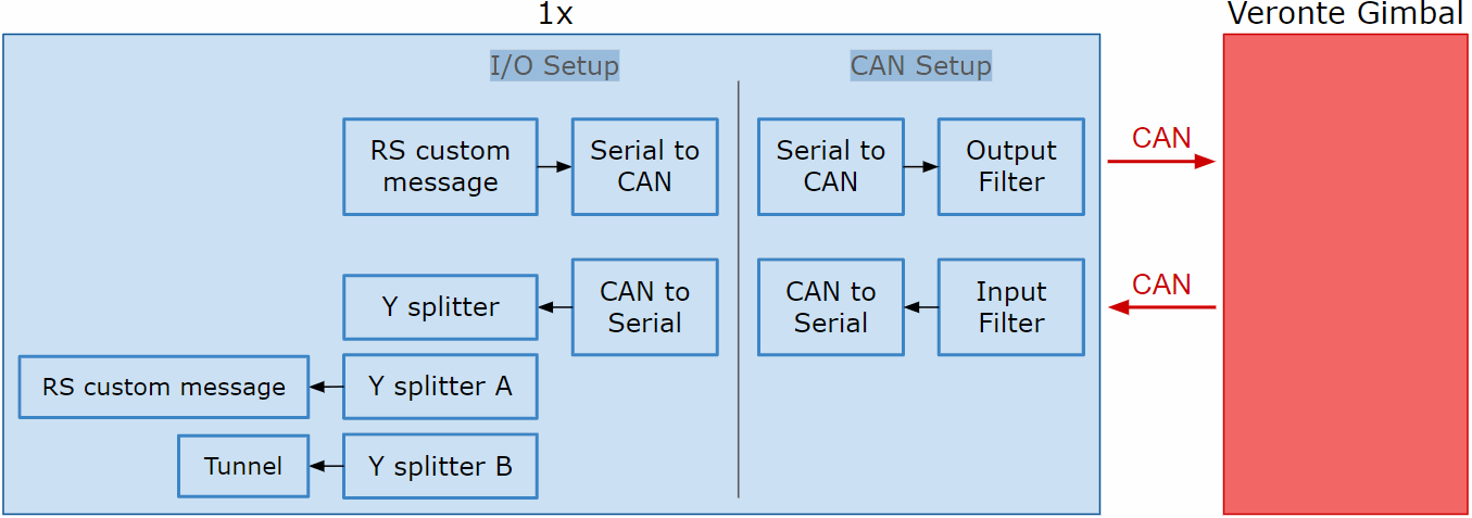
Communication with Veronte Gimbal camera video board
The following are the configuration aspects of the communication with the gimbal camera video board.
CAN commands sent by Autopilot 1x
-
In the Input/Output menu I/O Setup panel.
A RS custom message producer is connected to a Serial to CAN consumer. In this example, RS custom message 0 is connected to Serial to CAN 1.
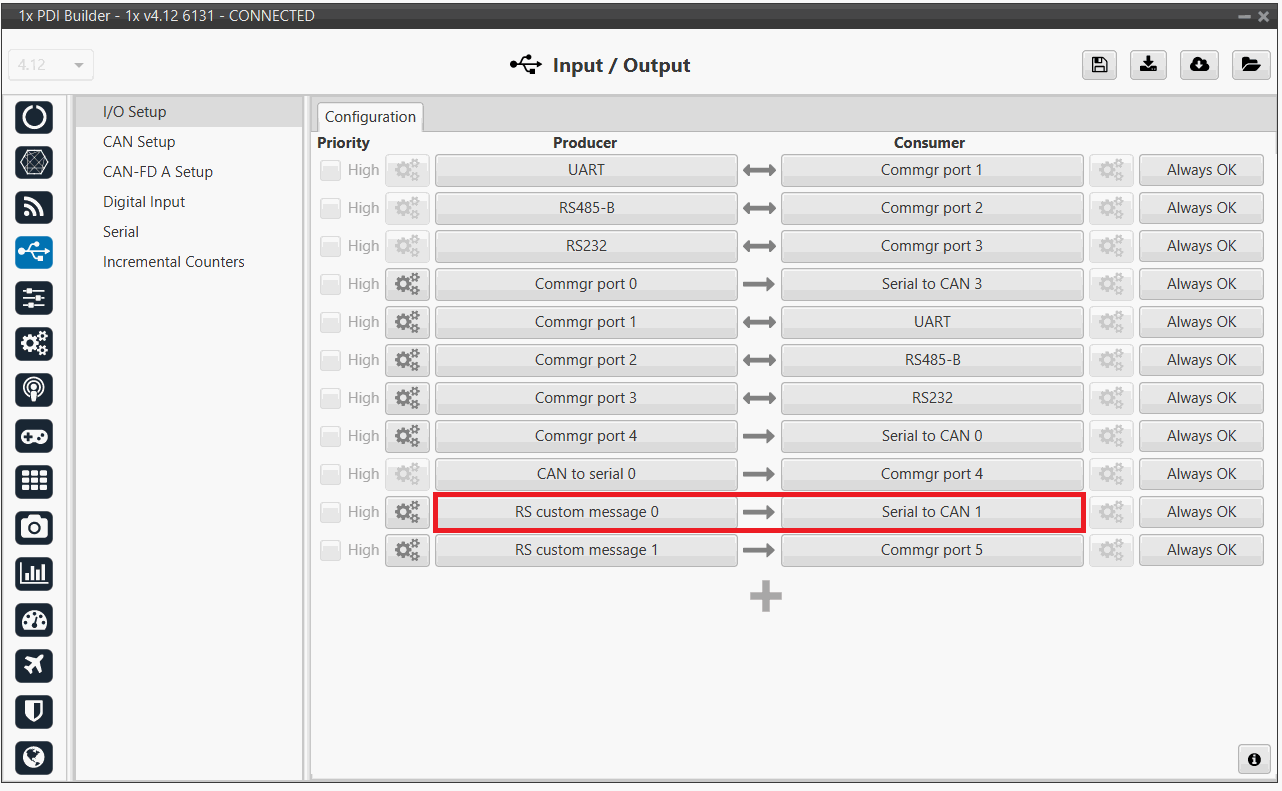
Veronte Gimbal - I/O Setup configuration panel Click on
 to access the RS custom message configuration.
It consists of 4 messages for request variables, i.e. they request information from the video board of the gimbal camera.
to access the RS custom message configuration.
It consists of 4 messages for request variables, i.e. they request information from the video board of the gimbal camera.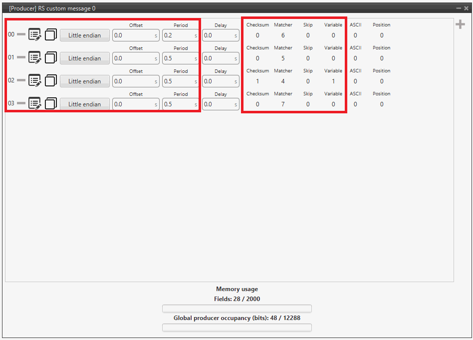
Veronte Gimbal - RS producer custom message configuration Message Endianness Period 00 Little endian 0.2 s 01 Little endian 0.5 s 02 Little endian 0.5 s 03 Little endian 0.5 s -
In the Input/Output menu CAN Setup panel Configuration tab.
A Serial to CAN producer with Id 1304 must be connected to an Output filter consumer. In this example, Serial to CAN 1 is connected to Output filter 1 and CAN A bus has been chosen.
Veronte Gimbal - CAN Setup configuration panel 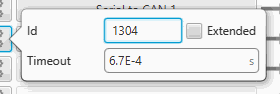
Veronte Gimbal - Serial to CAN configuration
CAN commands received on Autopilot 1x
-
In the Input/Output menu CAN Setup panel Configuration tab.
An Input filter producer with Id 1303 must be connected to a CAN to serial consumer. In this example, Input filter 1 configured to CAN A bus, is connected to CAN to serial 1.
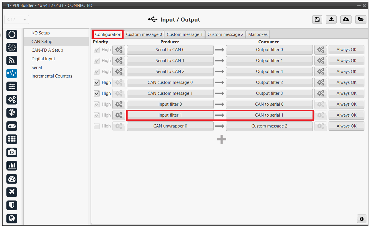
Veronte Gimbal - CAN Setup configuration panel 
Veronte Gimbal - Input filter configuration -
In the Input/Output menu CAN Setup panel Mailboxes tab.
20 reception mailboxes with ID 1303 are configured in CAN A bus (as the input filter has been configured to CAN A):
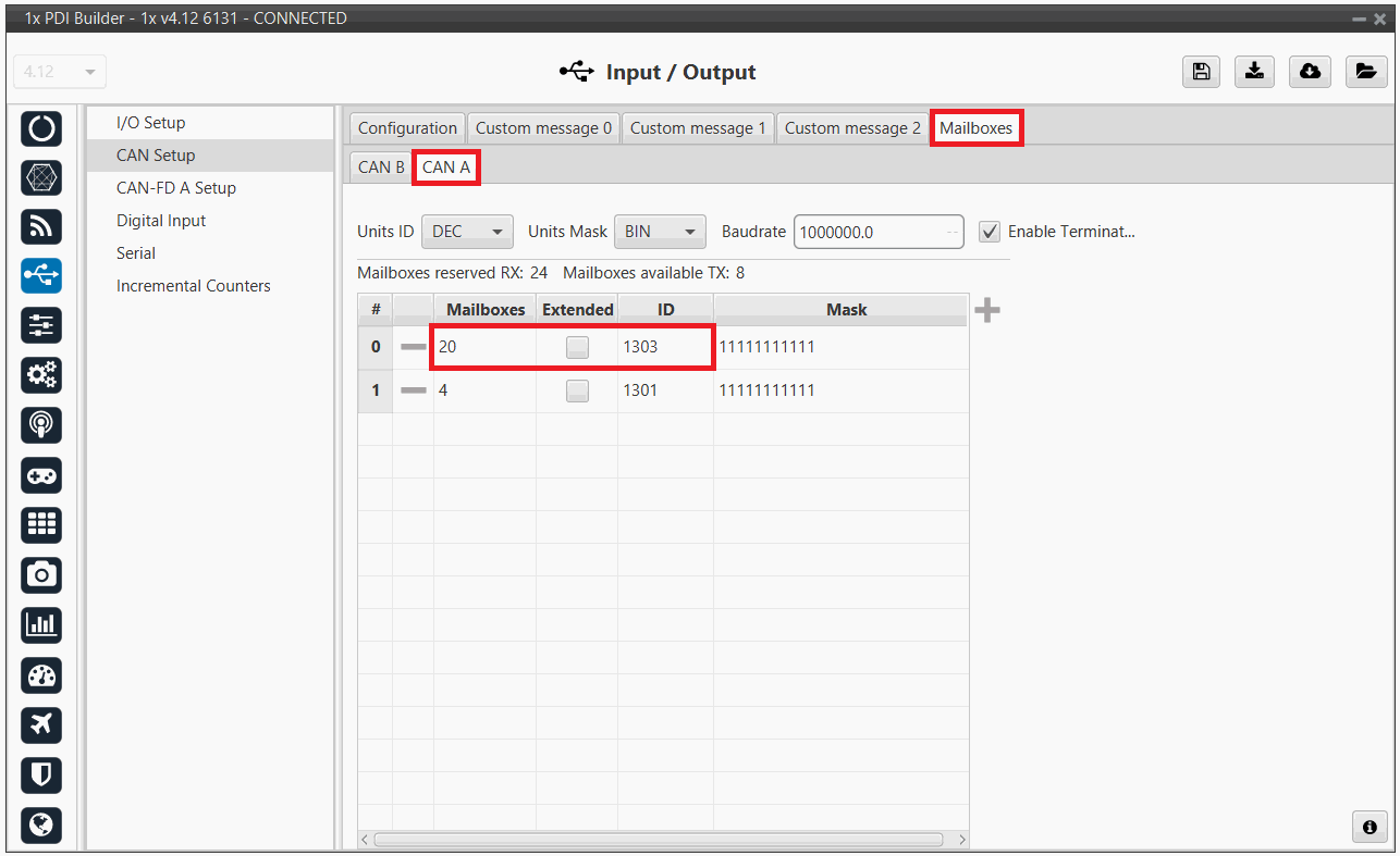
Veronte Gimbal - Mailboxes configuration -
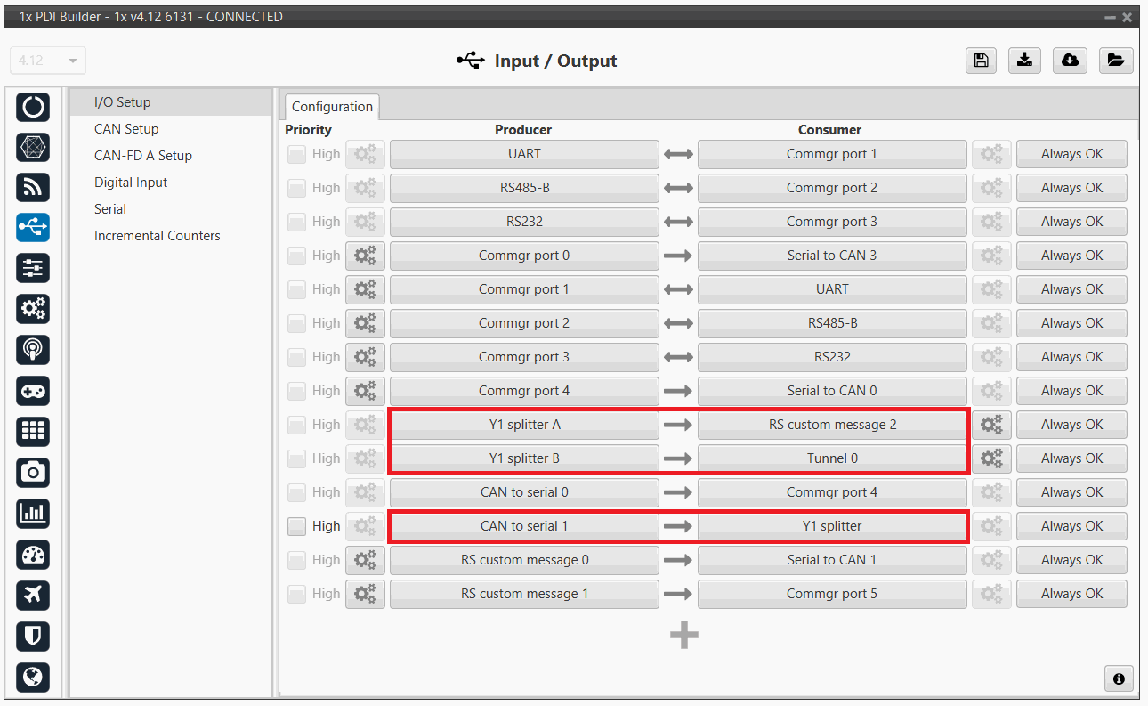
In the Input/Output menu I/O Setup panel.
A CAN to serial producer is connected to a Y splitter consumer. Then, a Y splitter A producer is connected to a RS custom message consumer and a Y splitter B producer is connected to a Tunnel consumer, configured to Address 2 (App) (App 2).
This connection is made in order to read and process the information received from the video board (RS custom message consumer) while sending this information to Veronte Ops. So Autopilot 1x is acting as a tunnel between the video board and Veronte Ops.
In this example, CAN to serial 1 is connected to Y1 splitter, Y1 splitter A to RS custom message 2 and Y1 splitter B to Tunnel 0.
Veronte Gimbal - CAN Setup configuration panel Click on
to access the RS custom message configuration.
It consists of 4 messages to read the video board information from the gimbal camera that has been previously requested.Important
They must be configured as Little endian.
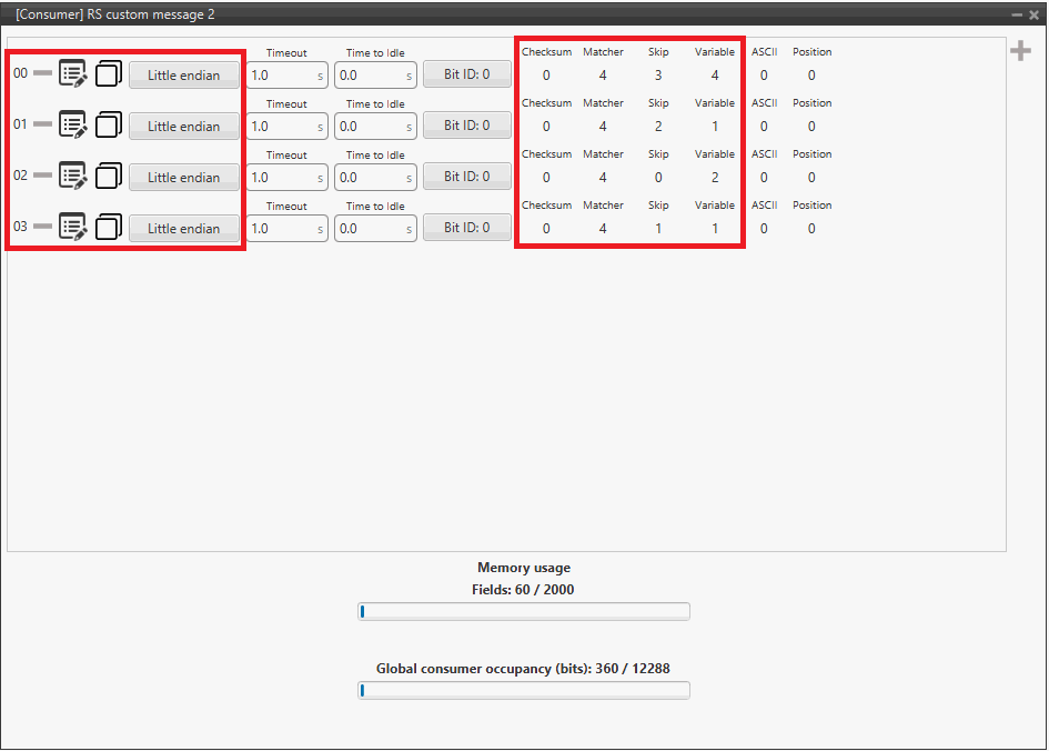
Veronte Gimbal - RS consumer custom message configuration Finally, click on
to access the Tunnel configuration: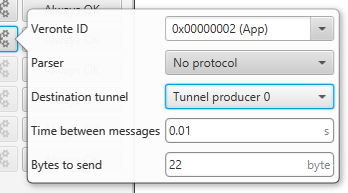
Veronte Gimbal - Tunnel configuration - Veronte ID: App
- Parser: No protocol
- Destination tunnel: Tunnel producer 0
- Time between messages: 0.01 s
- Bytes to send: 22 byte
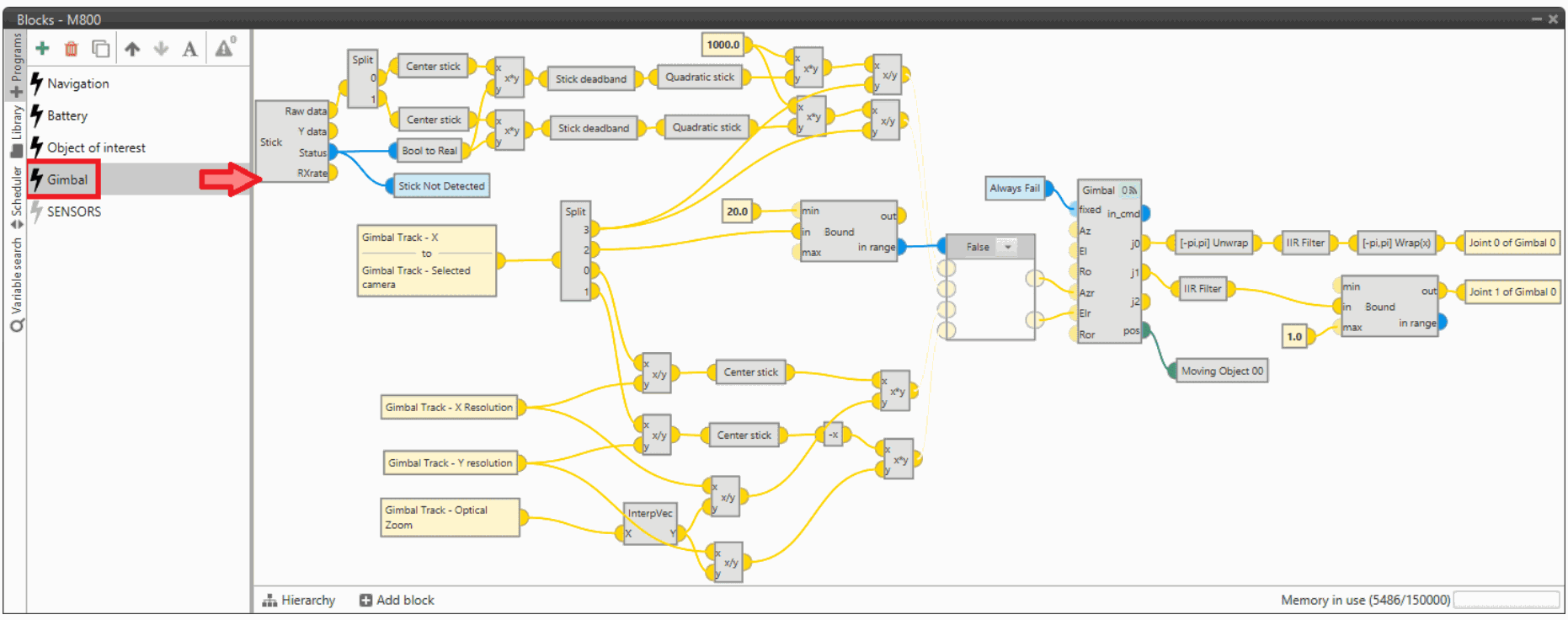
Gimbal block program
Finally, in the Block Programs menu, a Gimbal program has also been created to allow a correct communication between Veronte Autopilot 1x and the video board integrated in the Veronte Gimbal camera.
Warning
Users must add it to their own configuration in exactly the same way.
VSE (Veronte Stick Expander)
To configure the VSE in 1x PDI Builder it is only needed to follow the steps explained in the Ground unit configuration of the General case - PPM Stick integration example.
Important
In the step 1 of that explanation, there is already a transmitter configured with the required VSE configuration, users will find it as Brand: Embention and Model: Stick Expander.
The number of channels configured here must match those set in the VSE application. For more information on this, refer to the Channels - Software Installation section of the Stick Hardware Manual.
Furthermore, as the number of channels is modified, the Brand name will change to Customize.
© 2026 Embention. All rights reserved.