STANAG 4586
The STANAG 4586 panel is used to configure various communication messages, which represent the primary protocol for the autopilot's interactions. This interface allows the user to integrate specific messages one by one, making the process completely transparent within the firmware.
The STANAG 4586 panel is the interface dedicated to configuring interoperability protocols for Unmanned Aircraft Systems. This section allows for the mapping of internal system variables according to international standards, facilitating communication between the vehicle, the Ground Control Station (GCS), and other external assets.
The ![]() icon in the top right corner provides access to the following configuration sub-menus:
icon in the top right corner provides access to the following configuration sub-menus:
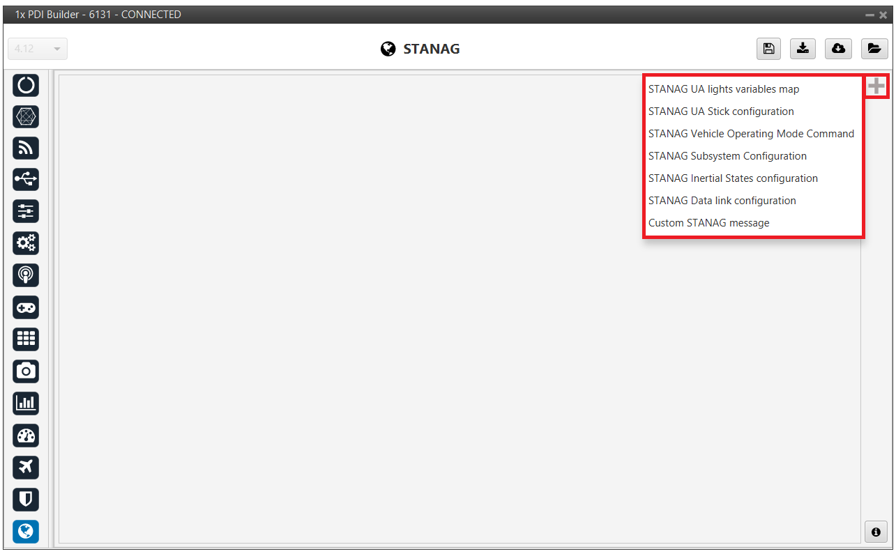
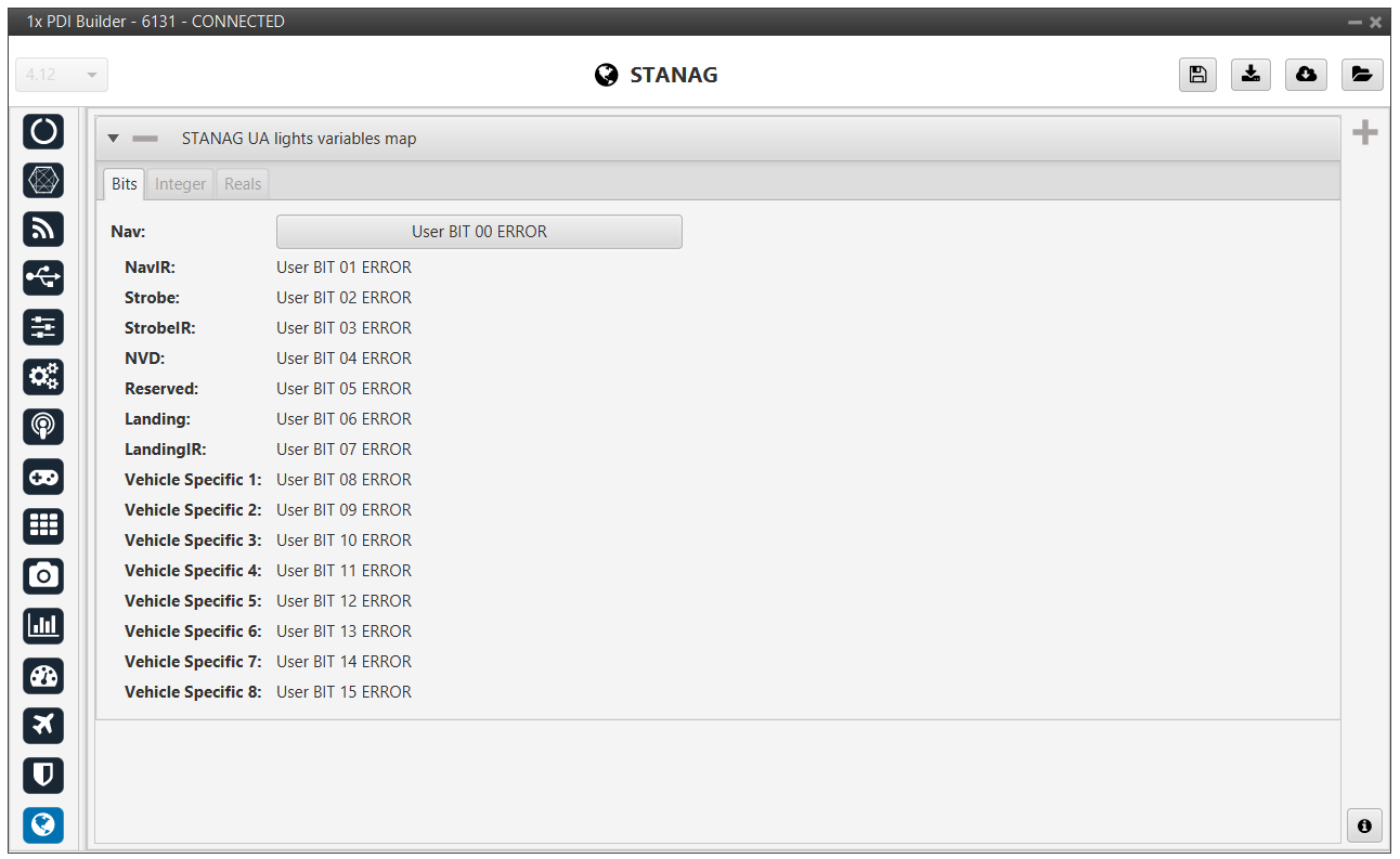
STANAG 4586 UA lights variables map
Used to map system state variables (e.g., strobe, navigation lights, landing lights) to commands defined by the STANAG 4586 standard.
-
Nav & Strobe: Controls for navigation and strobe lights (both visible and IR).
-
NVD & Landing: Indicators for Night Vision Devices (NVD) and landing lights.
-
Vehicle Specific (1-8): Customizable fields for vehicle-specific functions that fall outside the standard parameters.
Note
Light controls as a continuous data block.
STANAG 4586 UA Stick configuration
A section dedicated to mapping physical inputs (joystick/sticks) from the control station for manual or assisted vehicle piloting.
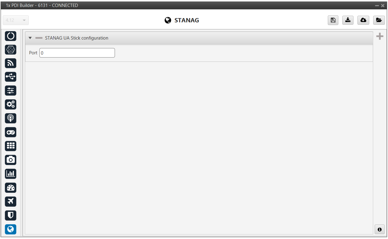
- Port: This field defines the logical communication index used to identify the specific STANAG 4586 data stream containing stick inputs. It allows the system to distinguish between multiple control sources or GCS instances, ensuring the commands are processed from the correct controller.
STANAG 4586 Vehicle Operating Mode Command
Configures the vehicle's operating modes so they are correctly interpreted by external command and control systems.
-
Integer panel:
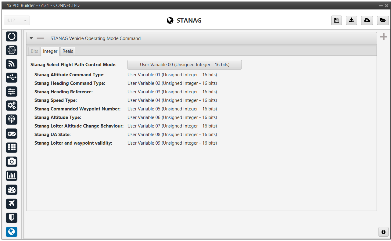
STANAG 4586 - Vehicle Operating Mode Command -
STANAG 4586 Select Flight Path Control Mode: Maps the variable that dictates the primary navigation method.
-
STANAG 4586 Altitude Command Type: Defines how the altitude commands are interpreted.
-
STANAG 4586 Heading Command Type: Assigns the variable for heading control.
-
STANAG 4586 Heading Reference: Sets the reference for heading data.
-
STANAG 4586 Speed Type: Maps the variable defining the speed reference.
-
STANAG 4586 Commanded Waypoint Number: Identifies the integer variable that tracks the active waypoint being targeted by the GCS.
-
STANAG 4586 Altitude Type: Specifies the reference for altitude data.
-
STANAG 4586 Loiter Altitude Change Behaviour: Defines how the aircraft transitions between altitudes while in a loiter pattern.
-
STANAG 4586 UA State: Maps the general operational state of the Unmanned Aircraft.
-
STANAG 4586 Loiter and waypoint validity: Links a variable that indicates whether the current navigation commands are valid and executable.
-
-
Reals panel:
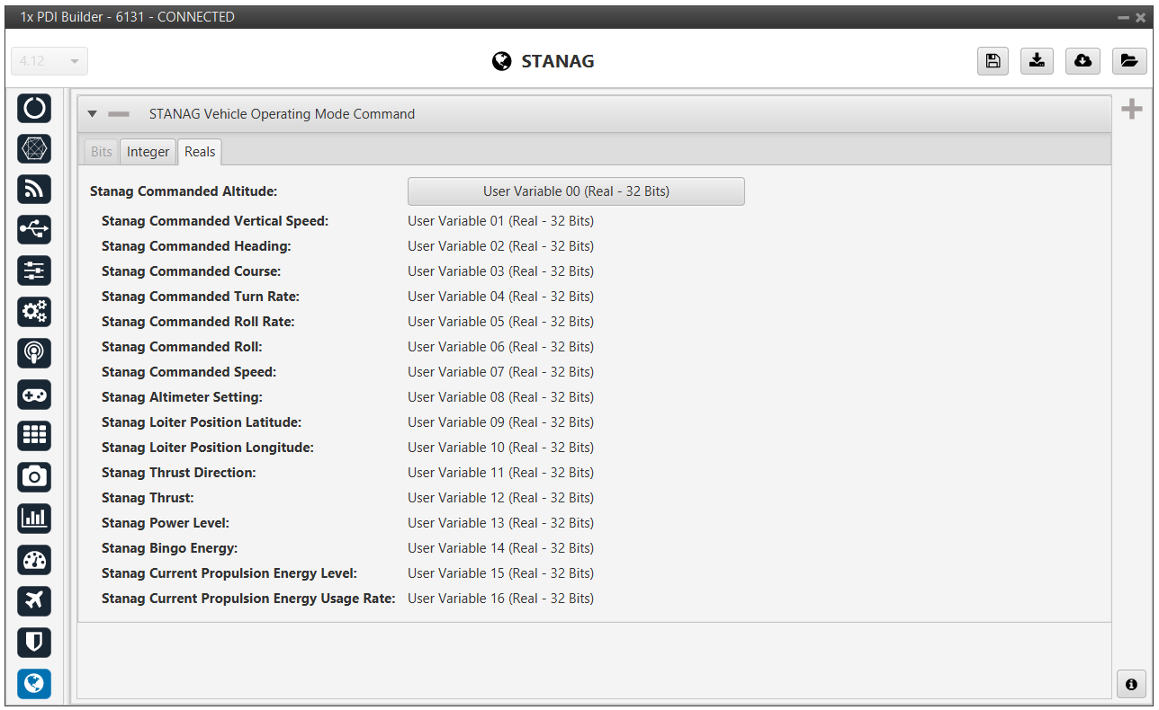
STANAG 4586 - Vehicle Operating Mode Command -
STANAG 4586 Commanded Altitude: The target altitude for the aircraft.
-
STANAG 4586 Commanded Vertical Speed: The desired rate of climb or descent.
-
STANAG 4586 Commanded Heading / Course: The target directional orientation or intended ground track.
-
STANAG 4586 Commanded Turn Rate / Roll Rate / Roll: Precision flight dynamic setpoints used during coordinated maneuvers or specific autopilot modes.
-
STANAG 4586 Commanded Speed: The target airspeed or ground speed for the mission.
-
STANAG 4586 Altimeter Setting: The pressure setting used to calibrate the aircraft's barometric altimeter.
-
STANAG 4586 Loiter Position Latitude / Longitude: The precise geographical coordinates for the center of a loiter pattern.
-
STANAG 4586 Thrust Direction / Thrust / Power Level: Parameters related to propulsion control and vectoring.
-
STANAG 4586 Bingo Energy: The critical energy threshold at which the aircraft must return to base.
-
STANAG 4586 Current Propulsion Energy Level / Usage Rate: Real-time monitoring of available energy and the instantaneous consumption rate.
-
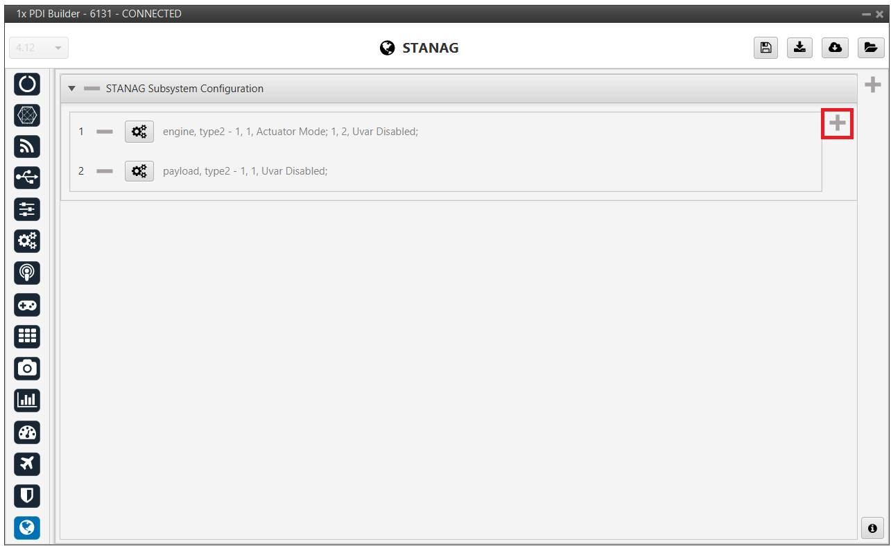
STANAG 4586 Subsystem Configuration
Allows for the management and status reporting of subsystems.
Click the ![]() icon to define additional subsystems.
icon to define additional subsystems.
Select the ![]() icon to configure the parameters.
icon to configure the parameters.
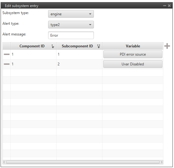
This window is used to create or modify the mapping between internal system errors and the standardized STANAG 4586 subsystem alerts. It ensures that when a specific component fails, the GCS receives a clear and categorized notification.
-
Subsystem type: Defines the category of the hardware being monitored (e.g., engine, mechanical, electrical).
-
Alert type: Specifies the severity or classification of the alert. This usually dictates how the GCS displays the warning.
-
Alert message: A text string that will be displayed on the GCS when the alert is triggered.
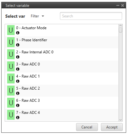
Click the ![]() icon, available variables can be viewed for selection.
icon, available variables can be viewed for selection.
STANAG 4586 Inertial States configuration
It maps data from the IMU and the Orientation and Directional Unit into the standard format for GCS visualization.
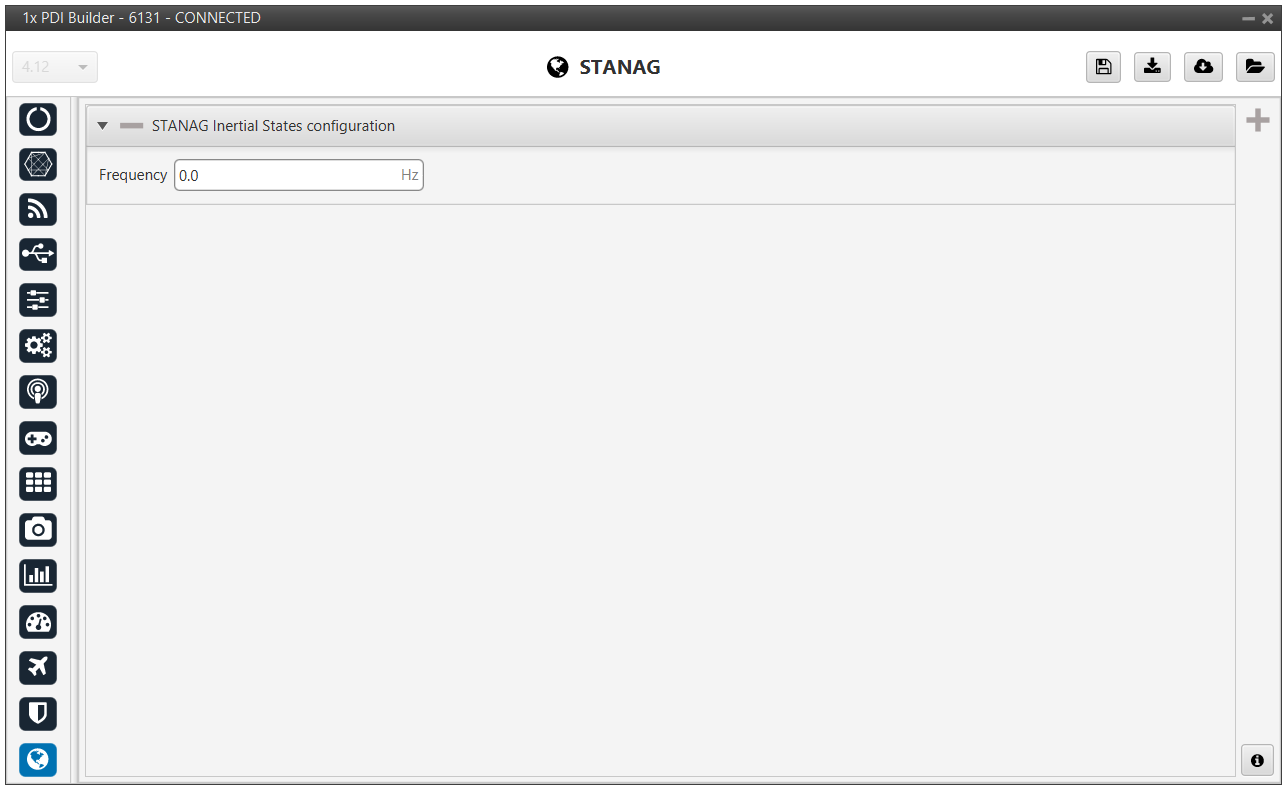
- Frequency: This field allows the user to set the update rate, measured in Hertz (cycles per second), for the transmission of inertial state messages.
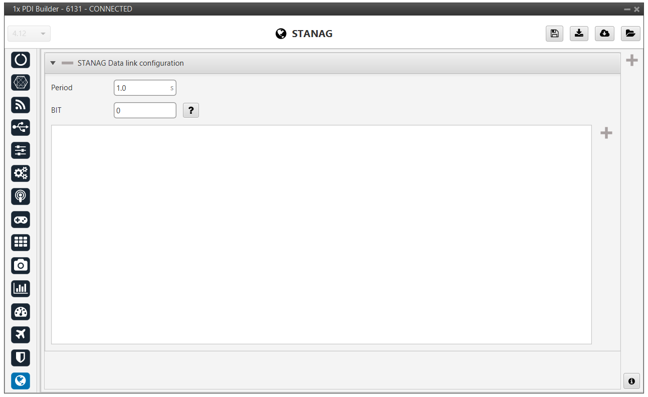
STANAG 4586 Data link configuration
Settings related to signal quality and network parameters of the data connection (Datalink), essential for monitoring signal stability.
-
Period: This field defines the time interval, measured in seconds, between each transmission of the data link status message.
-
BIT: This numerical field is used to assign or monitor the status of the Built-In Test associated with the data link hardware. It identifies specific internal test routines that verify if the communication hardware is functioning correctly.
Click the icon to display additional information.
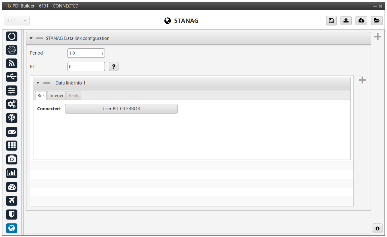
- Connected: This field defines the internal system variable that indicates the current connectivity status of the data link.
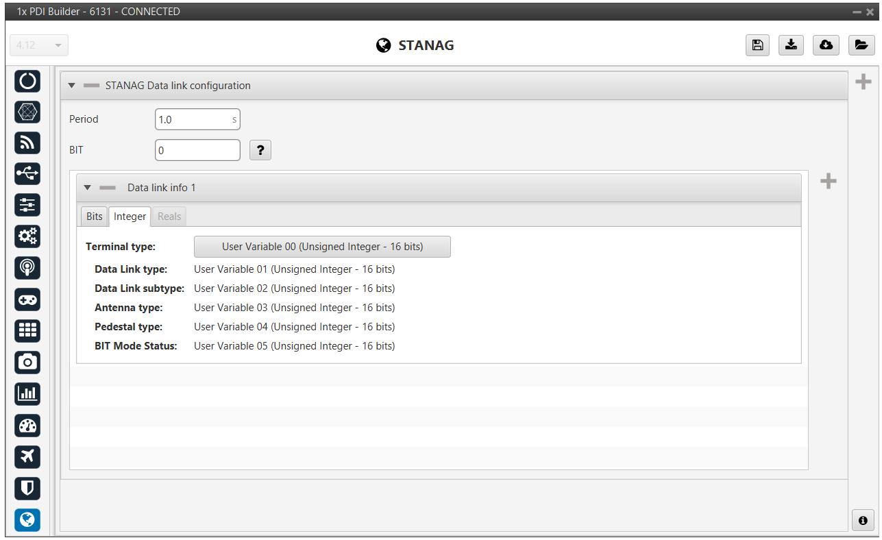
Terminal type: Maps the variable that identifies the specific model or class of the communication terminal.
-
Data Link type: Defines the primary technology of the link.
-
Data Link subtype: Provides further classification for the link type.
-
Antenna type: Identifies the hardware configuration of the antenna.
-
Pedestal type: Maps the variable for the antenna tracking system or gimbal base, if applicable.
-
BIT Mode Status: Tracks the current mode of the Built-In Test system.
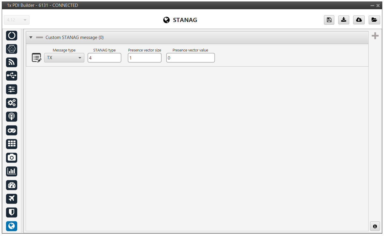
Custom STANAG 4586 message
Allows for the definition of personalized data packets that do not fall under standard categories while maintaining the STANAG 4586 protocol structure.
-
Message type: Defines the communication direction.
-
TX (Transmit): The vehicle sends this message to the GCS.
-
RX (Receive): The vehicle expects to receive this message from the GCS.
-
-
STANAG 4586 type: This numerical identifier specifies the unique ID assigned to the custom message within the protocol. This ID must match on both the aircraft and the Ground Control Station to ensure correct packet identification.
-
Presence vector size: Defines the size of the "presence vector," which tells the system which optional fields within the custom message are actually being used in a given transmission.
Presence vector value: Sets the default value for the presence vector.
© 2026 Embention. All rights reserved.