Connections
Here, you can configure the Input/Output ports of the autopilot. Depending on the selected port, different parameters will need to be provided.
Each connection is associated with a specific pin number. For more details, see the Pinout - Hardware Installation section of the 1x Hardware Manual.
ADC
ADC stands for Analog-to-Digital Converter. This connection is used by analog sensors. These sensors provide a voltage readout that needs to be converted into the actual measured variable, e.g., temperature, fuel volume, etc.
Autopilot 1x is equipped with 5 connections of this kind. Every ADC connection that is set requires an integer variable associated where the voltage readout will be stored. The maximum voltage of the ADC connection is 3.3 V.
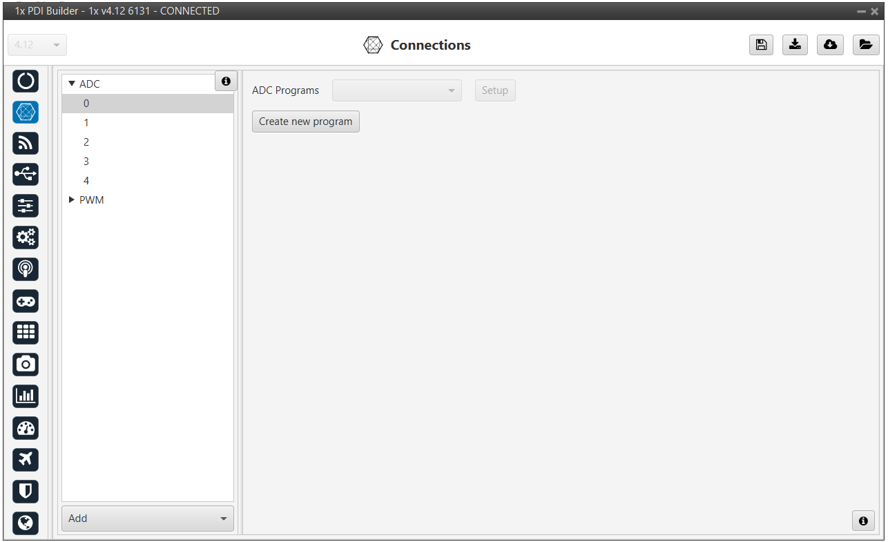
To convert the input ADC value to the physical variable it represents, the user needs to create a new program. See more information about programs in the Block Programs section of this manual.
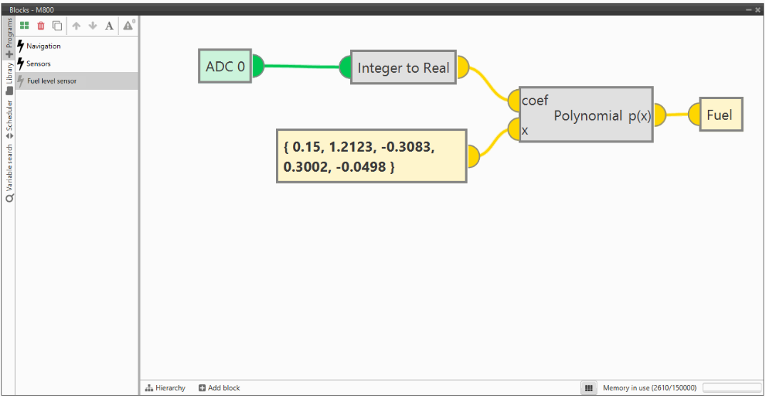
Application example
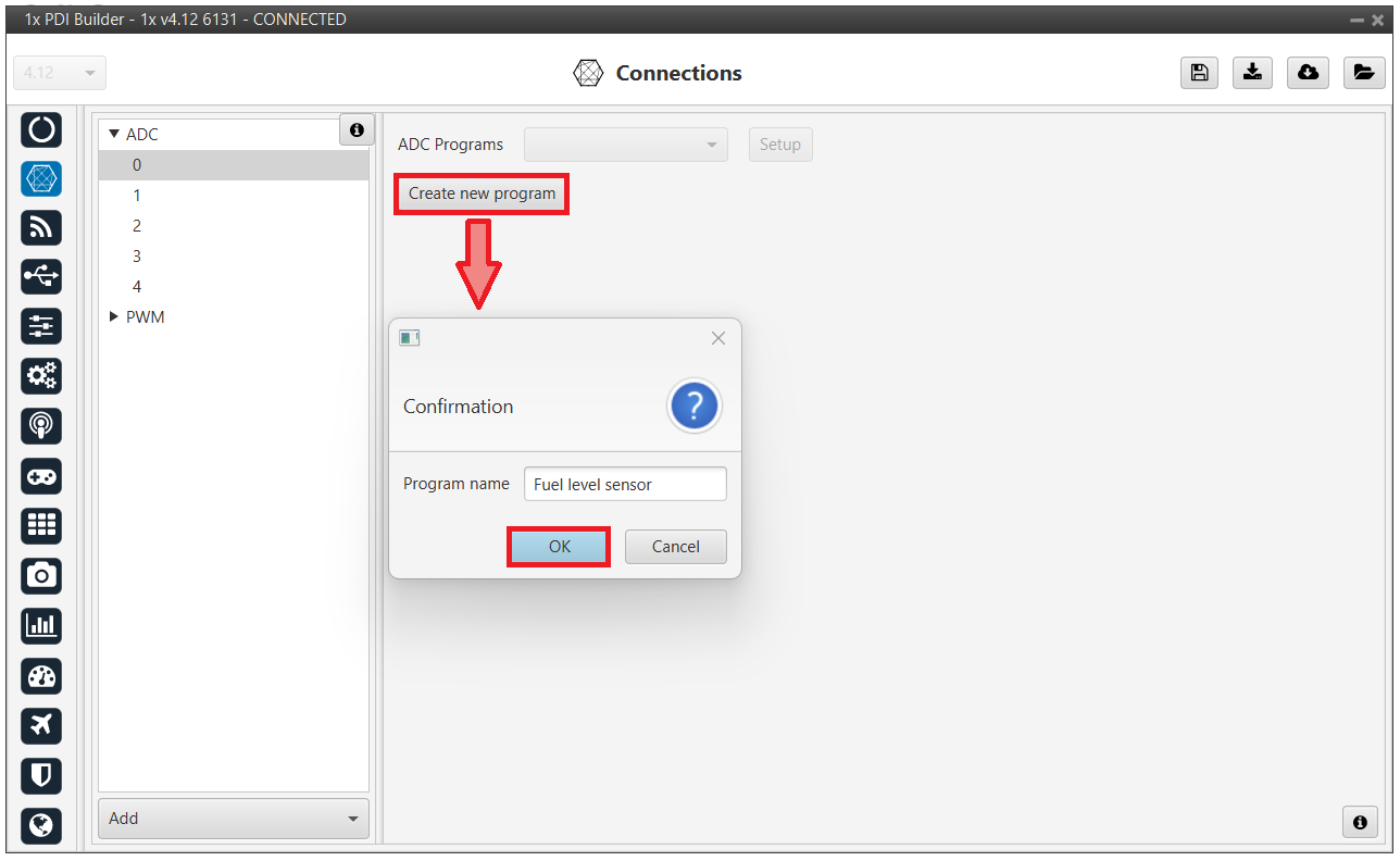
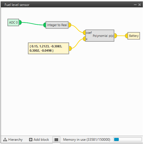
Let us consider a Fuel Level Sensor whose datasheet provides a direct relation of the voltage readout and the fuel volume (in L) through the polynomial , where is the fuel volume and is the sensor voltage.
Creating a new program, the above equation can be reproduced. An example of how to do it is presented below.
When the ADC program is created, a default block program is also created.
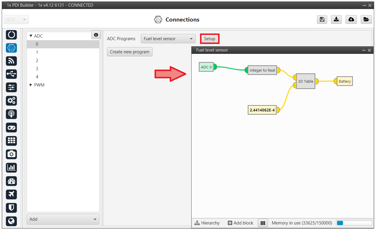
Now, the program has to be customized for this application. See more information about programs in the Block Programs section of this manual.
The fuel remaining in the tank is saved in a user variable, which can be used for displaying or warning purposes.
Note
- The ADC variable is first converted from integer to real, and then the polynomial is applied.
- This program can now be modified by clicking in 'Setup' in this menu or in the Block Programs menu.
PWM
Output pins produce PWM or I/O signals that are used to move the different servos and actuators of the platform.
The acronym PWM corresponds to Pulse Width Modulation. 1x sends a pulse with a certain width that is received by the servo/actuator, and according to the width of such pulse, it changes its behavior. A wide pulse will correspond to a big movement and a narrow one to a small movement.
By default, all PWM / I/O pins are configured as PWM output. So, to configure them as I/O, it is necessary to click Add:
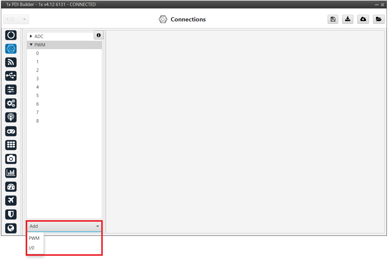
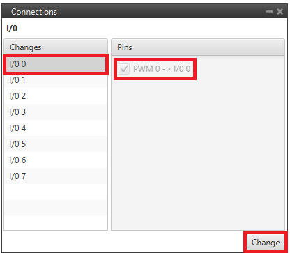
Then, select the I/O pin the user wants to change instead of PWM. As can be seen, pins are interchangeable.
Warning
Pins currently selected as I/O will not be displayed as they are not configurable in this mode. However, they can be reselected and reconfigured as PWM.
Note
When a pin is added as PWM, it is disabled as I/O and enabled as PWM. Hence, in the GPIO panel of Veronte menu, the "Function" parameter shall change to "Mux 1".
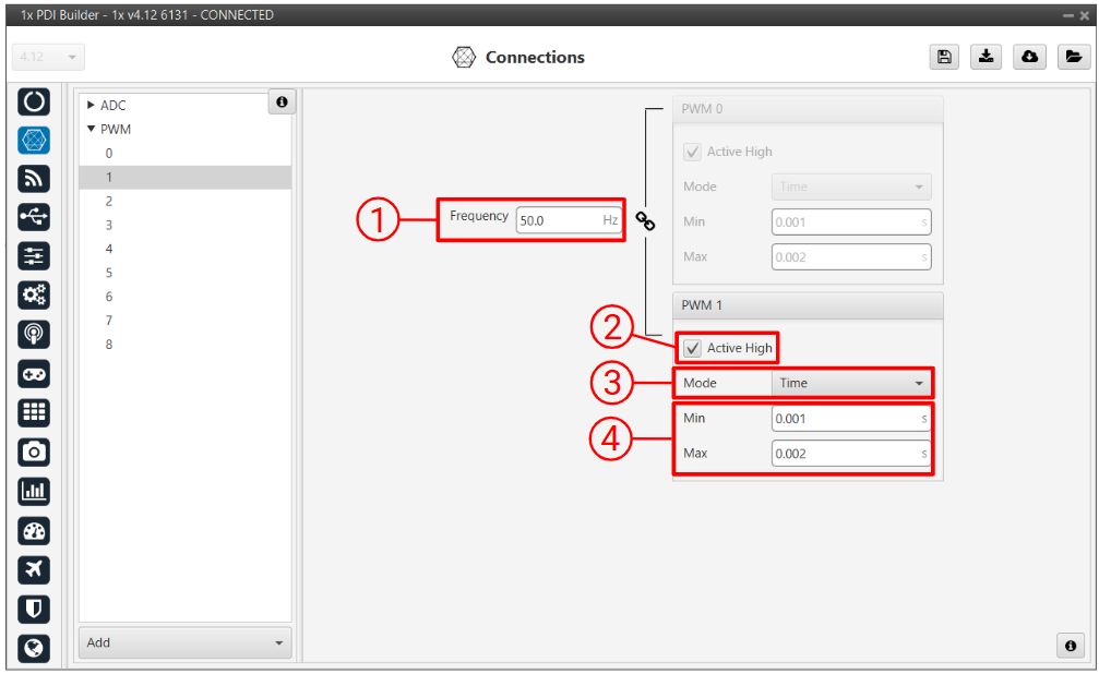
In this menu, the following parameters can be configured:
-
Frequency: PWM output frequency. This option determines the period of the pulses sent by the autopilot. The PWM is built in pairs inside the autopilot, and that is why the frequency is indicated in pairs, i.e. when the frequency of PWM 0 is changed, the one of PWM 1 also changes. The following table shows the PWM pairs as configured in Autopilot 1x.
PWM 0 PWM 1 PWM 2 PWM 3 PWM 4 PWM 5 PWM 6 PWM 7 PWM 8 PWM 9 PWM 10 PWM 11 PWM 12 PWM 13 PWM 14 PWM 15 PWM 16 PWM 17 PWM 18 PWM 19 -
Active High: Polarity high or low (high if enabled).
-
Mode: The available options are Time and Duty cycle.
-
Time: The values indicated in Min and Max parameters are expressed in time units.
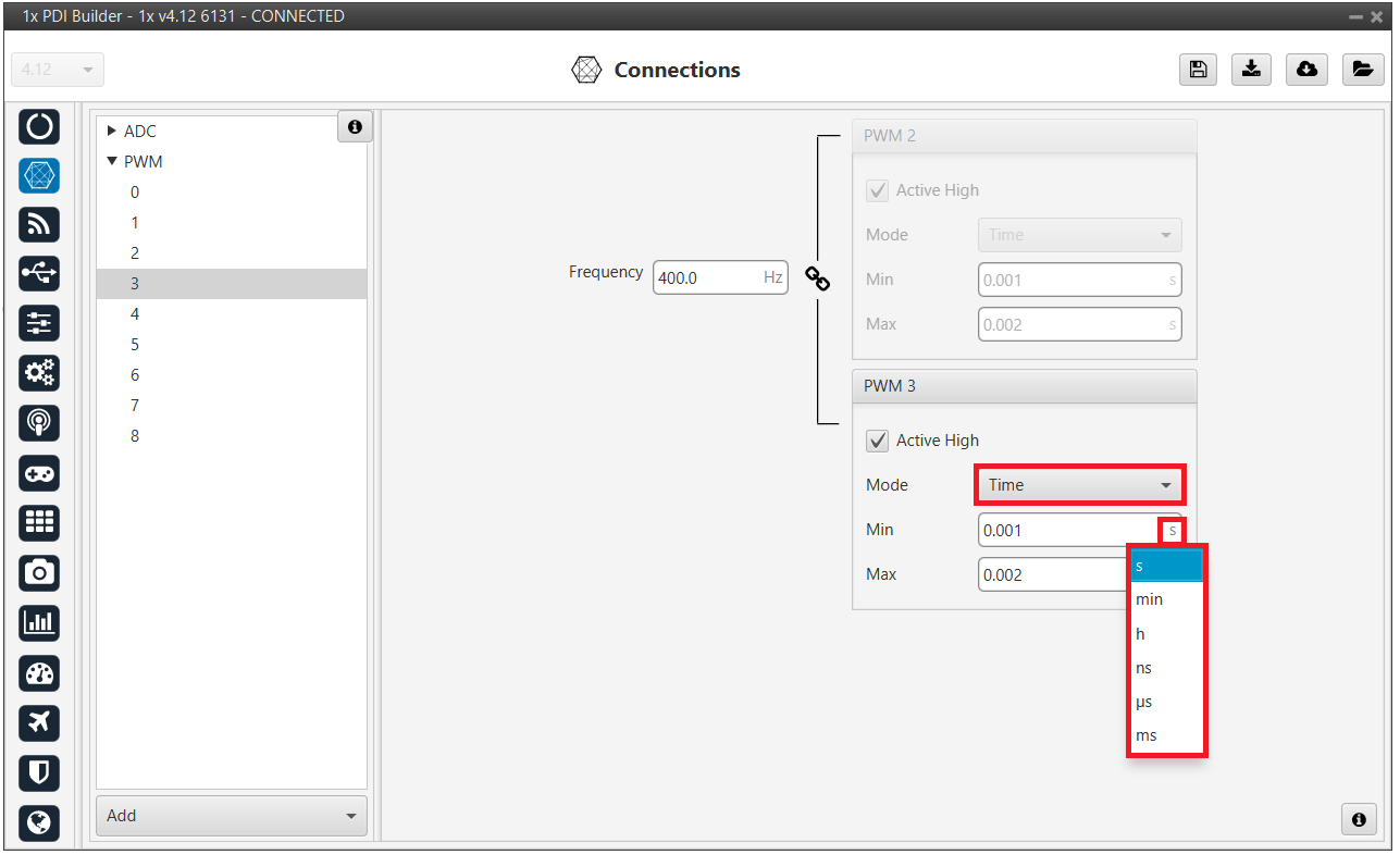
PWM panel - Time units -
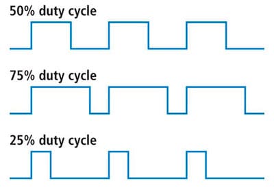
Duty cycle: This option is a different way of indicating the pulse width. Now the value indicated in Min and Max parameters is a percentage which corresponds to the relation between the pulse width over the total period of the sent signal.
So a 100% duty cycle will correspond to a signal with a constant value of 1, while a 0% duty cycle implies a constant signal with value 0. Between these two extremes, the pulse width can vary as in the examples shown in the following figure.
Duty cycle Note
Duty cycle percentages can be expressed in percent and per unit.
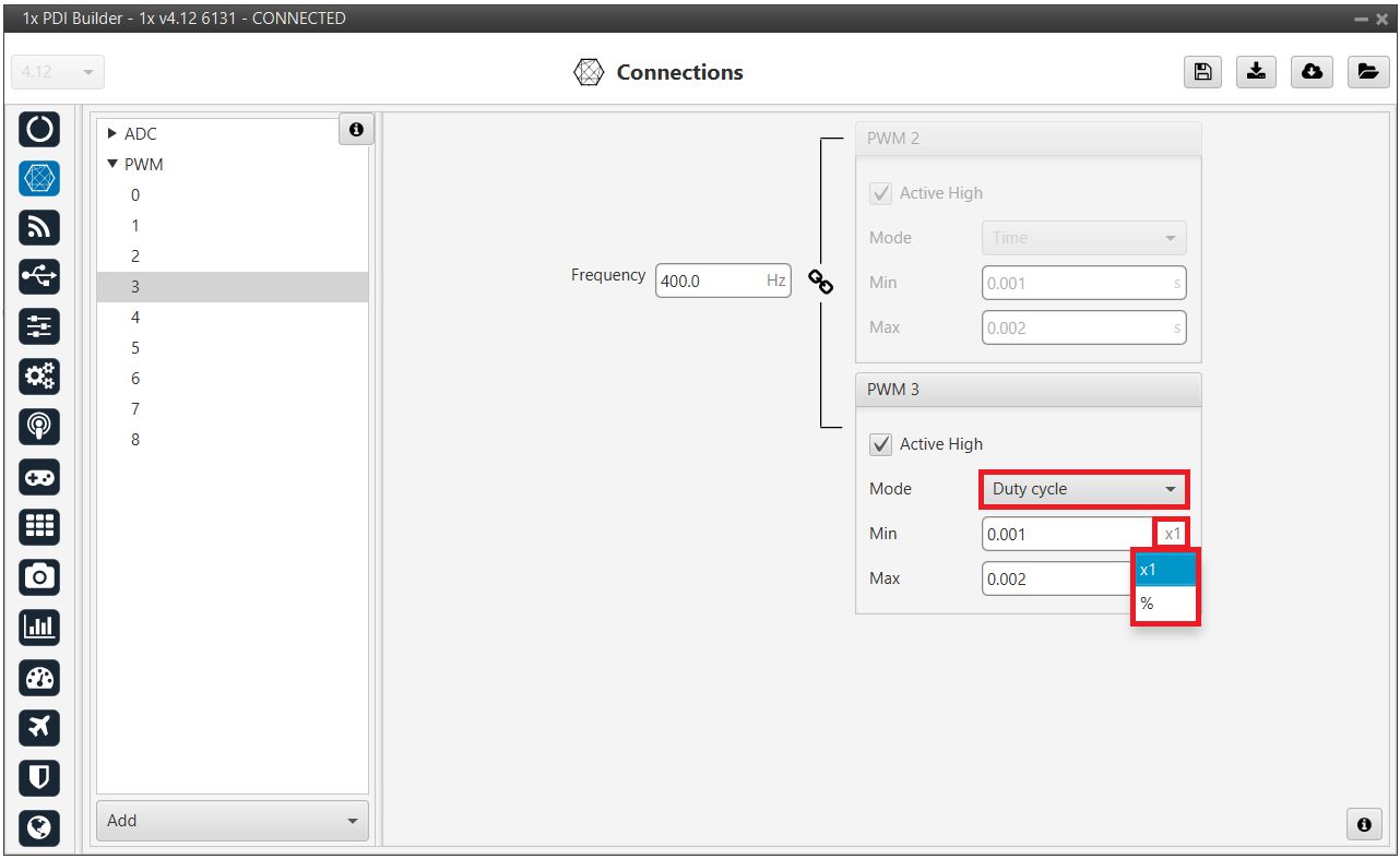
Duty cycle - percent
-
-
Min/Max: These parameters are the pulse width values that will make the servo/actuator go to its lowest/highest position. It will be the output when the PWM message specifies 0/4095.
As an example let's consider the servo of an aircraft elevator, a pulse sent by Autopilot 1x of 0.9 ms will correspond with the lowest point of the servo range (-30 degrees for example). On the other hand, a pulse of 2.1 ms will make the servo go to its top position (for example 30 degrees).
Summary
A PWM is a signal which consists of a series of pulses having a width determined by a percentage over a range specified by the parameters Min and Max. On the other hand, the I/O is a signal with a constant value (1,0) or with a single pulse (1,0).
© 2026 Embention. All rights reserved.