CORE 1
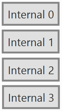
CORE 1 includes the blocks to interface inertial measurement units (IMU) such as Internal 0, Internal 1, Internal 2, and Internal 3 , which are necessary to detect the orientation and movement of the system.
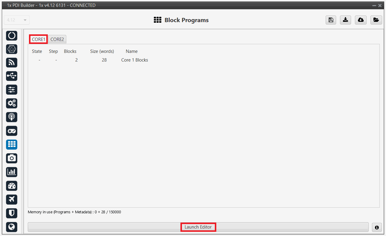
Click on Launch Editor to visualize the blocks.
Right-click and select "Edit" to view the configuration.
Common configuration
-
Maximum non-variation samples: Maximum number of samples with the same value, beyond which measurements are discarded. In case of failure, measurements are discarded.
-
Maximum allowed increment: Maximum increase in sensor measurement between one measurement and the next.
By clicking on the ![]() button, it is possible to add either a Low Pass or a Notch filter.
button, it is possible to add either a Low Pass or a Notch filter.
-
Low Pass:
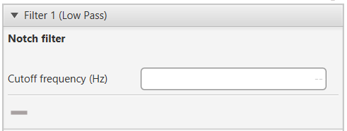
Filter - Low Pass - Cutoff Frequency (Hz): Defines the center frequency where the filter is applied.
-
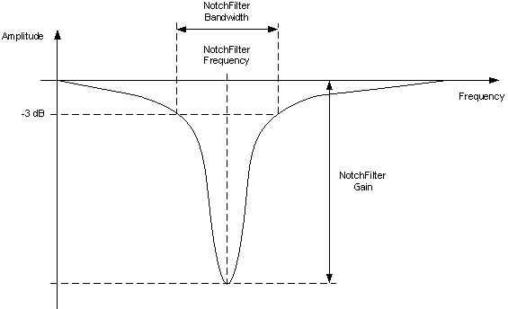
Notch Filter:
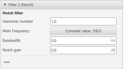
Filter - Notch Notch filter is a filter that dampens signals only at a specific frequency. - Harmonic Number: Allows the filter to target specific harmonics of the main frequency. - Main Frequency: Main frequency (Hz) at which the notch filter reaches its maximum damping.
Warning
When a user variable is used to set this frequency, it must be initialized to a value other than 0, otherwise a PDI error will occur.
-
Bandwidth: Design parameter. There is a damping of at least 3 dB within the bandwidth. The main frequency at which the maximum damping (notch gain) is reached, lies in the center of this spectrum.
-
Notch gain: Design parameter. This parameters sets the maximum damping (dB) for the main frequency.
Note
Setting this parameter to zero disables the filter.
Notch filter -
Internal 0-1
The Internal 0-1 manages the sensor connected to communication port 0-1.
-
Accelerometer
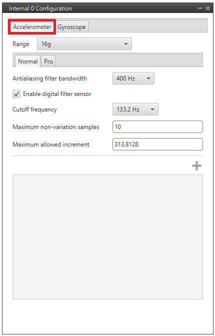
Internal 0-1 - Configuration - Range: Selectable range of forces that the accelerometer can measure, high ranges implies less precision while small ranges might mean the system saturates.
Values allowed are 2g, 4g, 8g and 16g.
-
Antialising filter bandwith: It is the bandwidth of the antialiasing low pass filter.
The options available are 50Hz, 100Hz, 200Hz and 400Hz, the greater the value selected the worse the filtering will be. -
Enable digital filter sensor: Enables a low pass filter which its cutoff frequency is configured from the options 16.65Hz, 66.6Hz, 133.2Hz and 740.0Hz.
This is a hardware filter, included directly in the accelerometer.
-
Gyroscope
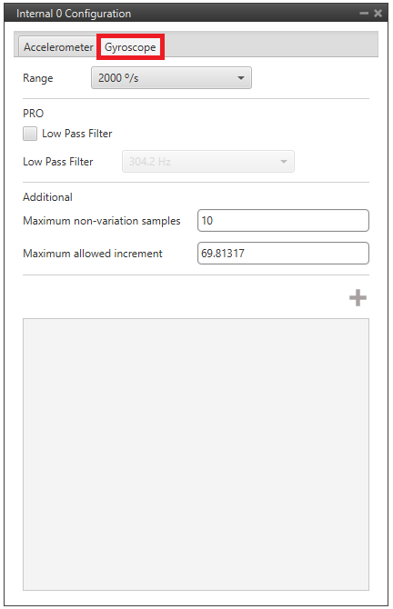
Internal 0-1 - Configuration -
Range: Sets the maximum range of performance, high ranges implies less precision while small ranges might mean the system saturates.
Values allowed are 125°/s, 250°/s, 500°/s, 1000°/s and 2000°/s. -
Low Pass Filter: Filter that attenuates high frequencies to clean the signal from noise and mechanical vibrations, stabilizing the sensor's reading.
Values allowed are 12.5 Hz, 25.1 Hz, 49.8 Hz, 99.6 Hz, 166.6 Hz, 220.7 Hz, 304.2 Hz and 435.2 Hz.
The common configuration parameters are not explained again.
-
Internal 2
Internal 2 block dedicated to reading data from the inertial measurement unit, commonly used for standard navigation and attitude applications.
-
Accelerometer:
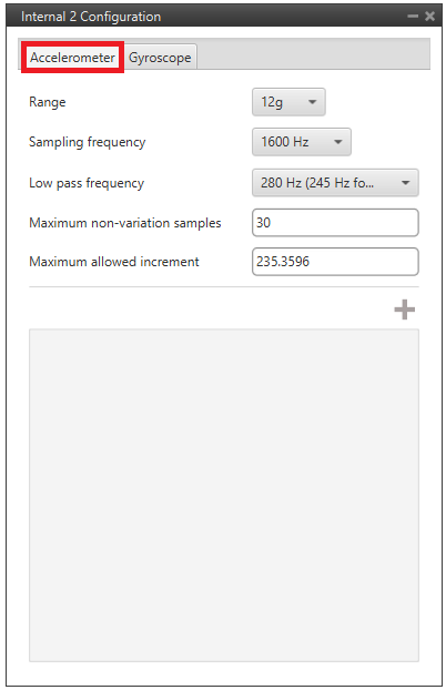
Internal 2 - Configuration - Range: Selectable range of forces that the accelerometer can measure, high ranges implies less precision while small ranges might mean the system saturates.
Values allowed are 3g, 6g, 12g and 24g.
-
Sampling frequency: That is the frequency at which the measurements are read out. Values allowed are 12.5Hz, 25Hz, 50Hz, 100Hz, 200Hz, 400Hz, 820Hz and 1600Hz. We recommend the highest.
-
Low pass frequency: This is a hardware filter, included directly in the accelerometer, which its cutoff frequency is configured from the options 145Hz, 234Hz (215Hz for Z axis) and 280Hz (245Hz for Z axis).
-
Gyroscope:
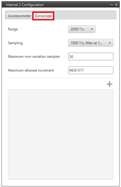
Internal 2 - Configuration -
Range: Sets the maximum range of performance, high ranges implies less precision while small ranges might mean the system saturates.
Values allowed are 125°/s, 250°/s, 500°/s, 1000°/s and 2000°/s. -
Sampling: That is the angular velocity at which the measurements are read out. Values allowed are 100°/s filter at 32 Hz, 200°/s filter at 64 Hz, 100°/s filter at 12 Hz, 200°/s filter at 32 Hz, 400°/s filter at 47 Hz, 1000°/s filter at 116 Hz, 2000°/s filter at 230 Hz and 2000°/s filter at 532 Hz.
The common configuration parameters are not explained again.
-
Internal 3
Internal 3 block manages the interface with the high-precision inertial sensor.
-
Accelerometer:
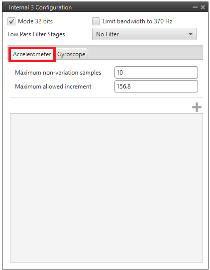
Accelerometer - Configuration -
Mode 32 bits: Enable or disable. With 32 bits of precision. We recommend enabling it.
-
Limit bandwith to 370Hz: Enable or disable. It can only be used without using a Low Pass Filter Stages. We recommend disabling it.
-
Low Pass Filter Stages: IMU's Hardware filter. The options available are:
- No filter
- 1 stage (Cutoff f=364Hz)
- 2 stages (Cutoff f=165Hz)
- 3 stages (Cutoff f=80Hz)
- 4 stages (Cutoff f=40Hz)
- 5 stages (Cutoff f=20Hz)
- 6 stages (Cutoff f=10Hz)
We recommend 4 stages (Cutoff f=40Hz) option.
Warning
- It is recommended to choose the hardware filter (Low Pass Filter) except if a lower cutoff frequency is needed (< 10 Hz).
- It is not recommended flying without a filter.
-
-
Gyroscope:
The configuration of the Gyroscope is analogous to that of the Accelerometer.
The common configuration parameters are not explained again.
© 2026 Embention. All rights reserved.