Control blocks
Control blocks are those related to the creation of control loops.
PID
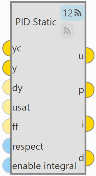
PID Static block allows the user to build a PID (Proportional, Integral and Derivative) controller with fixed gains.
As can be seen in the figure above, PID Static block has 2 ![]() buttons that enable or disable the block to be commanded from the 1x PDI Tuning
software.
buttons that enable or disable the block to be commanded from the 1x PDI Tuning
software.
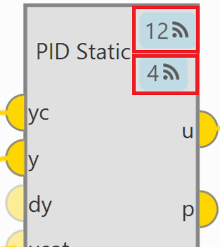
The first button is for activating 'Command PID' and the second one is for the 'Autotune' command. For more information on these commands, please refer to the Tuning section of the 1x PDI Tuning user manual.
Each command button has a different ID that allows the user to identify it during the command.
Note
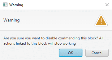
To avoid disabling a block by mistake, the following warning message appears when disabling it:
-
The PID mathematical implementation in Veronte Autopilot 1x is the following:
Where:
-
Inputs
 yc: Target value, desired set-point of the controlled variable. y: Closed loop, value of the controlled variable. (Optional) dy: Derivative of the controlled variable (computed numerically from 'y' if not connected). (Optional) usat: Previously applied control action after saturation (used for anti-windup and respect).
If not connected a value of zero is assumed. (Optional) ff: Feed-forward control, this value is added to the 'u' output before applying the output limits.
If not connected a value of zero is assumed.
yc: Target value, desired set-point of the controlled variable. y: Closed loop, value of the controlled variable. (Optional) dy: Derivative of the controlled variable (computed numerically from 'y' if not connected). (Optional) usat: Previously applied control action after saturation (used for anti-windup and respect).
If not connected a value of zero is assumed. (Optional) ff: Feed-forward control, this value is added to the 'u' output before applying the output limits.
If not connected a value of zero is assumed. (Optional) respect: When TRUE the output 'u' is equal to the input 'usat' and the integral component is estimated with the information in 'y' and 'yc'.
When FALSE the PID works as usual. If not connected a value of FALSE is assumed. (Optional) enable integral: When TRUE the the PID works as usual. When FALSE the integral is exponentially discharged.
If not connected a value of TRUE is assumed.
(Optional) respect: When TRUE the output 'u' is equal to the input 'usat' and the integral component is estimated with the information in 'y' and 'yc'.
When FALSE the PID works as usual. If not connected a value of FALSE is assumed. (Optional) enable integral: When TRUE the the PID works as usual. When FALSE the integral is exponentially discharged.
If not connected a value of TRUE is assumed. -
Outputs
u: Control output after applying PID limits. p: Proportional part of the output before the PID limits are applied. i: Integral part of the output before the PID limits are applied. d: Derivative part of the output before the PID limits are applied. -
Configuration menu:
Double click on the block to open its configuration menu.
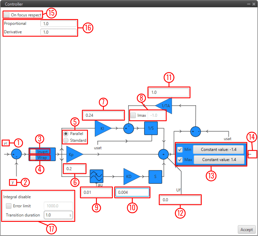
PID block configuration - yc: Input variable.
- y: Feedback variable.
- Invert: Apply a -1 gain .
- Wrap: Perform a [-pi, pi] wrap.
- Parallel/Standard: In parallel mode, PID gains are independent. In standard mode, I & D gains are scaled by P gain.
- KP: Proportional gain.
- 1/TI: Integral gain.
- Imax: Maximum value for integral term. Value must be possitive and the limit applied is symmetrical ([-Imax, Imax]).
- tau: Time constant for the derivative term first order LPF.
- TD: Derivative gain.
- TA: Anti-windup gain. Recommended value around x10 KI. Unloads integral term if output is saturated.
- Uf: Output offset. Feedforward value is also applied at this point.
- Min/Max: Output limits. Users can manually enter a value or select a variable.
- u: PID output.
- On focus respect: If respect is enabled, when the PID is first executed, an initial I value will be applied so that 'u' = 'usat' for the first iteration.
- Proportional/Derivative Beta: yc scaling for proportional and derivative terms. Unless necessary, value should always be 1.
- Integral disable: Disables integral term if (yc - y) > Error limit.
Tip
Remember to always use 'wrap' for direction controllers, such as 'Heading' or 'Yaw' PIDs. This will allow the UAV to always turn in the right direction.
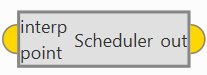
Scheduler
Scheduler block is a multidimensional look-up table interpolator with no extrapolation. This block is used to output a data array based on an input interpolation point.
- Input
![]() interp point: Interpolation point provided as an array of N dimensions (where N corresponds to the number of independent variables defined in the table).
interp point: Interpolation point provided as an array of N dimensions (where N corresponds to the number of independent variables defined in the table).
- Output
![]() out: Interpolated data array resulting from the look-up operation.
out: Interpolated data array resulting from the look-up operation.
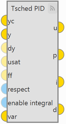
T-Sched PID
TSched PDI block is a PID (Proportional, Integral and Derivative) controller with table scheduled parameters. It allows to scale most PID parameters using an external variable, usually the speed (Ground speed or IAS).
It works in a very similar way to the PID Static block, except that in that block the gains are fixed and in the TSched block they are adjusted for different values of the input variable.
For this reason, the inputs and outputs are the same, but in this block an additional input is added:
-
Input
var: Scaling variable for gain scheduling used to interpolate in the table to obtain the PID parameters.
-
Configuration menu
Double click on the block to open its configuration menu.
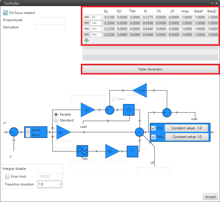
TSched PID block configuration In this block, the PID gains for the different values of the input variable must be entered in the table above instead of in the diagram. To add more values, simply click on
 and to remove them, click on
  .
.If the variable is outside the limits, the values of the closest point will be applied. Values between points are linearly interpolated.
In addition, clicking on "Table Generator" will bring up another configuration menu:
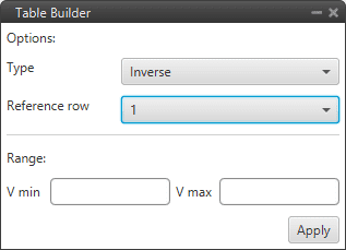
TSched PID block configuration - Table Generator This is another option to enter the PID gains for different values of the input variable, instead of manually entering all the gains, the Table Generator will generate them according to the parameters to be configured:
-
Type: Depending on the type of function selected, the gains are calculated differently.
- Inverse: It will calculate the different gains with an inverse function.
- Proportional: It will calculate the different gains with a proportional function.
- Quadratic: It will calculate the different gains with a quadratic function.
Type Result (Kp) Inverse Kpi VVi Proportional Kpi ViV Quadratic Kpi Vi2V2 -
Reference cow: Users must select the reference values from which the other values will be calculated.
- Range: The minimum and maximum values of the input variable between which the gains have to be calculated have to be defined.
Then just click on "Apply" and the maximum number of points that the table allows will be generated.
-
Example
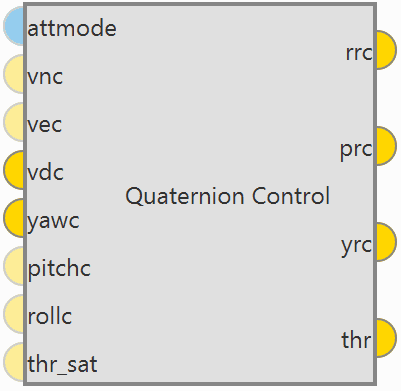
Quaternion Control
Quaternion Control block for fixed multirotor aircraft.
-
The Quaternion Control mathematical implementation in Veronte Autopilot 1x is the following:
-
The quaternion control algorithm calculates the desired direction and magnitude of the thrust vector of a multicopter in order to achieve the desired NED velocities, these generate a three-component acceleration vector in NED coordinates, which is compared with the actual direction of the thrust vector to obtain a quaternion representing the rotation from the actual to the desired thrust.
The error is applied to a control law determined by a time constant that provides the body angle rates to achieve the desired acceleration.
-
In addition, the algorithm is divided in two quaternion calculations depending on the yaw being controlled or not:
- Reduced: Only the crucial angles of the thrust desired vector are considered. The yaw is not controlled directly.
- Full: Both the pointing direction of the vector and the yaw is controlled.
-
-
Inputs
(Optional) attmode: Flag for velocity (hover) or angle (hold) control.
If true only the angles will be controlled, if false or not connected the velocity of the aircraft will be controlled. (Optional) vnc: Desired north velocity (only used if velocity mode is active). Assumed zero if not connected. (Optional) vec: Desired east velocity (only used if velocity mode is active). Assumed zero if not connected. vdc: Desired down velocity. yawc: Desired yaw. (Optional) pitchc: Desired pitch (only used if angle mode is active). Assumed zero if not connected. (Optional) rollc: Desired roll (only used if angle mode is active). Assumed zero if not connected. (Optional) thr_sat: Saturated thrust from previous step. Used for respect and antiwindup. -
Outputs
rrc: Desired p (Angular Velocity - X Body Axis). prc: Desired q (Angular Velocity - Y Body Axis). yrc: Desired r (Angular Velocity - Z Body Axis). thr: Desired thrust. -
Configuration menu:
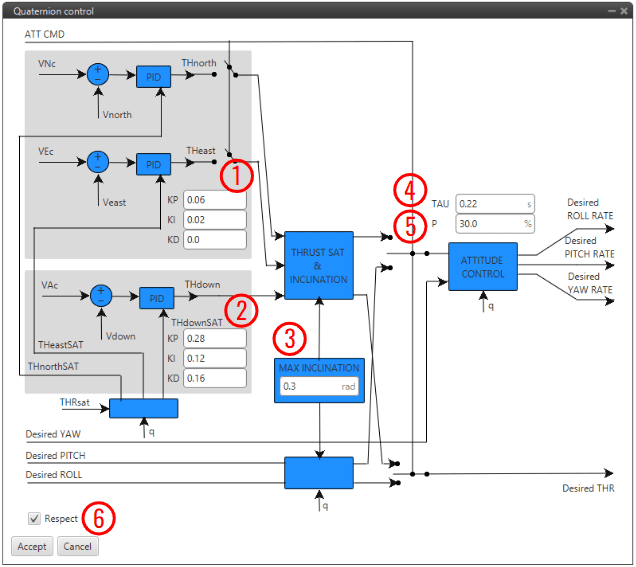
Quaternion Control block configuration As this block is mainly constituted by 3 PID controllers (for more information, see PID block), only some relevant parameters are detailed below:
- PID to transform desired velocities into desired accelerations in NED.
- PID to transform the vertical velocity into desired acceleration.
- MAX INCLINATION: Maximum inclination allowed to the aircraft.
- TAU: Time constant of the system. It is also the gain used for the feedback controller. Recommended values between 0.1 and 0.25 seconds.
-
P: Reduction factor indicating how the yaw is to be controlled compared to pitch and roll.
The idea is that the "yaw control power" is lower in a multicopter as it is controlled by angular momentum difference between motors while pitch and roll is controlled by thrust difference. By default, it is configured to 30%.
-
Respect: If enabled, when the block is executed for the firs time, an initial I value will be applied so that 'thr' = 'thr_sat' for the first iteration.
Furthermore, the thrust is assumed to be between 0 and 1. In case the user has other values for the thrust, it is recommended to use an Interpolation block at the input and output to adjust the range between 0 and 1.
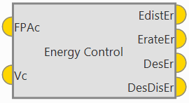
Total Energy Control
Total Energy Control block has been designed for the decoupling of the control of the speed and FPA in fixed-wing aircrafts. This block uses the internal navigation estimation.
It will provide two errors that must be minimized in order to obtain the desired speed and flight path:
- Energy Distribution Error: Distribution of sistem energy between kinetical and geopotential energy. This error shall be used to control the aircraft's pitch or FPA.
- Energy Rate Error: Rate of change of the Total System Energy. This error accounts for the necessary increase or decrease in thrust.
The outputs Desired energy rate and Desired distribution energy rate are useful as feed forward in control.
-
Inputs
FPAc: Desired FPA (Flight Path Angle) set-point. Vc: Desired velocity set-point. Depending on the block configuration the velocity can be IAS or Ground Speed. -
Outputs
EdistEr: Energy distribution error for pitch control. ErateEr: Energy rate error for thrust control. DesEr: Desired energy rate. DesDisEr: Desired distribution energy rate. -
Configuration menu:
Some parameters of the Energy algorithm can be modified by double clicking on the block:
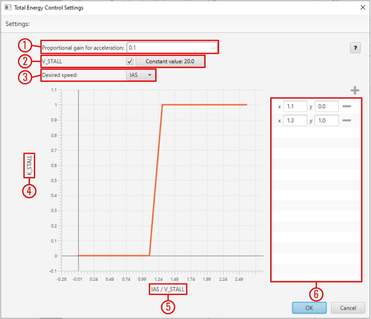
Energy Control block configuration -
Proportional gain for acceleration: This is an indication of how aggresive the algorithm is when trying to gain speed.
The higher the value, the faster the algorithm will try to 'dive' in order to gain speed.
A typical recommended value is around 0.1-0.3. Higher values are only recommended for fast maneuvering platforms.
-
V_STALL: Stall velocity parameter can be enabled or disabled. Users can manually enter this value or select a variable.
- Desired speed: The user must choose between IAS and GS (Ground Speed) for reference. The use of GS is not recommended unless Airspeed measurement is not available.
- K_STALL: Stall correction coefficient. If 1, energy control is balanced for altitude and speed. If 0 only speed control is taken into account.
- IAS/V_STALL: Speed/Stall ratio. Ratio between current speed and minimum speed.
-
Stall correction interpolation function: Defines how the relationship between the stall correction coefficient and the Speed/Stall ratio works.
The default configuration (as shown in the figure above) is recommended.
Note
The Stall correction coefficient is a Safety tool that can be used to sacrifice altitude control in order to improve speed control when speed gets close to the stall velocity (V_STALL) defined above.
-
© 2026 Embention. All rights reserved.