CAN-FD A SETUP
Mailboxes
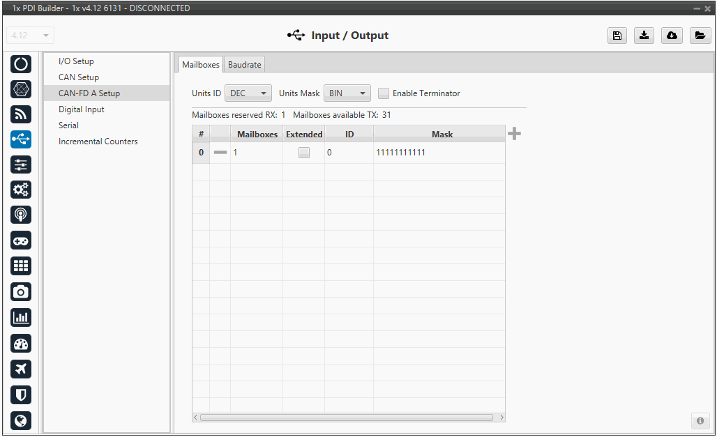
Main screen to configure the baudrate and reception mailboxes of the CAN-FD A bus.
Since Veronte Autopilot 1x receives data on the CAN-FD Bus, it is mandatory to configure a certain number of mailboxes to store that data until the system reads it. A mailbox can be configured for multiple CAN message IDs as long as the mask is correctly set and messages are sent with enough spacing for the core to process them.
In order to add a mailbox, press the + icon.
The configurable parameters are:
-
Units ID: Display units for the ID (Decimal, Hexadecimal, or Binary).
-
Units Mask: Display units for the Mask (Decimal, Hexadecimal, or Binary).
-
Enable Terminator: Allows enabling the internal CAN resistor via software.
-
Mailboxes: Number of mailboxes assigned to that specific configuration.
-
Extended: If enabled, the frame format uses a 29-bit identifier. Otherwise, the 'Standard' 11-bit identifier is used by default.
-
ID: The identifier used for RX messages (11-bit or 29-bit).
-
Mask: A filter for reception; the mask defines which parts of the incoming message ID must match the configured ID. Only binary digits set to '1' in the mask are compared.
Baudrate
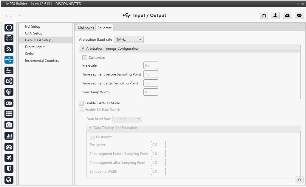
The Baudrate tab within the CAN-FD A Setup menu allows users to define the specific timing and speed parameters for the CAN Flexible Data-rate bus. CAN-FD distinguishes itself by allowing two different bit rates: one for the arbitration phase and another for the data phase.
-
Arbitration Baud rate: A dropdown menu to select the base communication speed.
-
Arbitration Timings Configuration: By enabling the Customize checkbox, users can manually define the low-level timing segments of the bit:
-
Pre-scaler: Sets the time quantum length.
-
Time segment before/after Sampling Point: Defines the position of the sampling point within the bit time to ensure stable data reading.
-
Sync Jump Width: Defines the maximum time synchronization adjustment.
-
-
Enable CAN-FD Mode: This checkbox must be enabled to use the Flexible Data-rate frame format.
-
Enable Bit Rate Switch: When active, the bus will switch to a higher speed during the data payload section of the frame.
-
Data Baud Rate: Sets the high-speed rate for the data phase.
-
Pre-scaler: Defines the "time quantum," the base unit of time used to build the bit segments.
-
Time segment before Sampling Point: Sets the duration of the phase preceding the sampling point; correct configuration ensures signal stability when the bit is read.
-
Time segment after Sampling Point: Defines the phase duration after the sampling point to manage propagation delays on the bus.
-
Sync Jump Width: Specifies the maximum compensation the system can apply to resynchronize with other nodes in case of phase variations.
-
© 2026 Embention. All rights reserved.