CORE 1
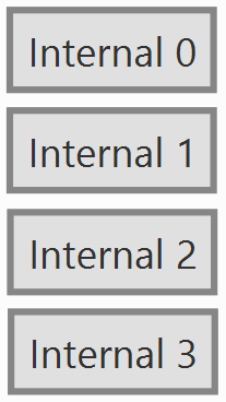
CORE 1 includes the blocks to interface inertial measurement units (IMU) such as Internal 3 (ADIS165053), Internal 2 (BMI088), and Internal 0-1 (Lsm6dsx on port 0-1), which are necessary to detect the orientation and movement of the system.
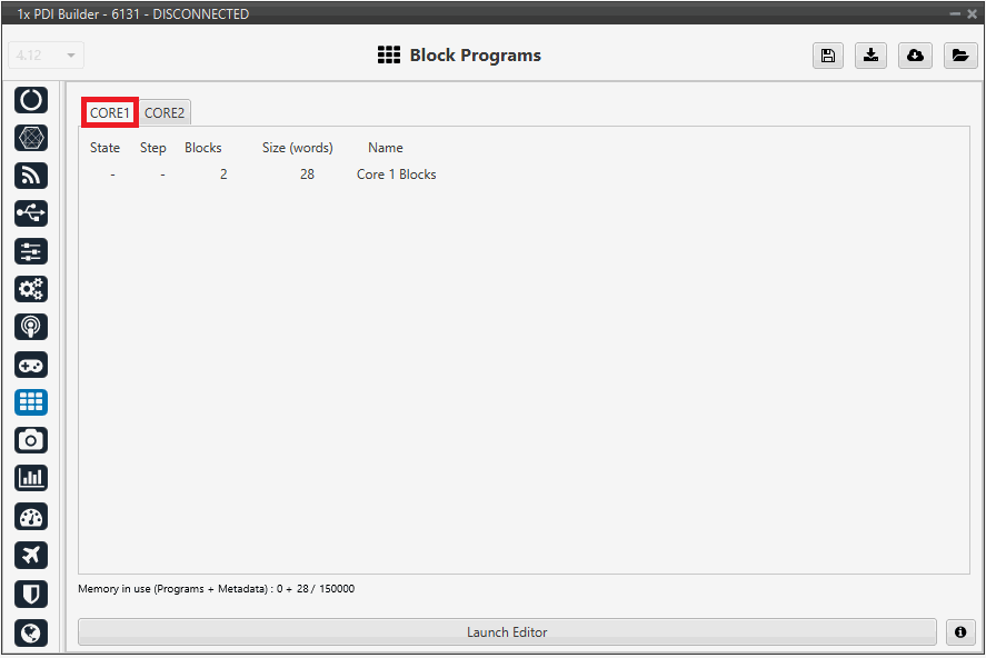
Click on Launch Editor to visualize the blocks.
-
Internal 0-1 (Lsm6dsx on port 0-1): Manages the sensor connected to communication port 0-1.
-
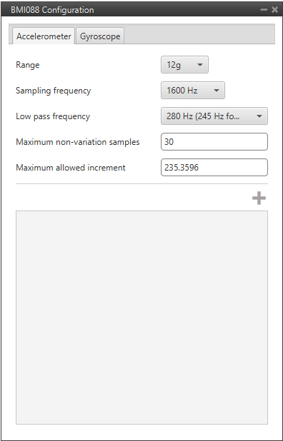
Internal 2 (BMI088): A block dedicated to reading data from the BMI088 inertial measurement unit, commonly used for standard navigation and attitude applications.
-
Internal 3 (ADIS165053): This block manages the interface with the ADIS165053 high-precision inertial sensor.
Right-click and select "Edit" to view the configuration.
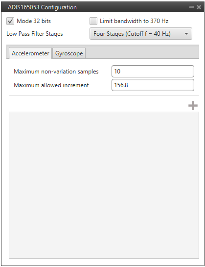
- Maximum non-variation samples: Maximum number of samples with the same value, beyond which measurements are discarded. In case of failure, measurements are discarded.
- Maximum allowed increment: Maximum increase in sensor measurement between one measurement and the next.
-
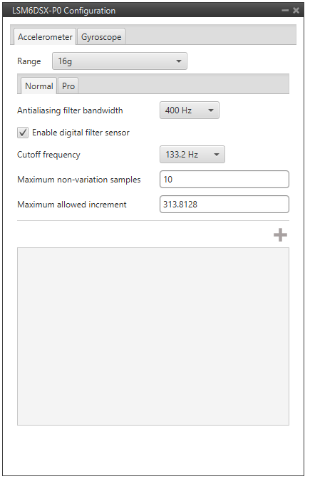
Range: Selectable range of forces that the accelerometer can measure, high ranges implies less precision while small ranges might mean the system saturates.
Values allowed are 3g, 6g, 12g and 24g.
-
Sampling frequency: That is the frequency at which the measurements are read out. Values allowed are 12.5Hz, 25Hz, 50Hz, 100Hz, 200Hz, 400Hz, 820Hz and 1600Hz. We recommend the highest.
- Low pass frequency: This is a hardware filter, included directly in the accelerometer, which its cutoff frequency is configured from the options 145Hz, 234Hz (215Hz for Z axis) and 280Hz (245Hz for Z axis).
- Maximum non-variation samples: Maximum number of samples with the same value, beyond which measurements are discarded. In case of failure, measurements are discarded.
- Maximum allowed increment: Maximum increase in sensor measurement between one measurement and the next.
-
Antialising filter bandwith: It is the bandwidth of the antialiasing low pass filter. The options available are 50Hz, 100Hz, 200Hz and 400Hz, the greater the value selected the worse the filtering will be.
-
Enable digital filter sensor: Enables a low pass filter which its cutoff frequency is configured from the options 16.65Hz, 66.6Hz, 133.2Hz and 740.0Hz.
This is a hardware filter, included directly in the accelerometer.
-
Maximum non-variation samples: Maximum number of samples with the same value, beyond which measurements are discarded. In case of failure, measurements are discarded.
-
Maximum allowed increment: Maximum increase in sensor measurement between one measurement and the next.
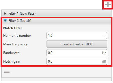
By clicking on the ![]() button, it is possible to add either a Low Pass or a Notch filter.
button, it is possible to add either a Low Pass or a Notch filter.
-
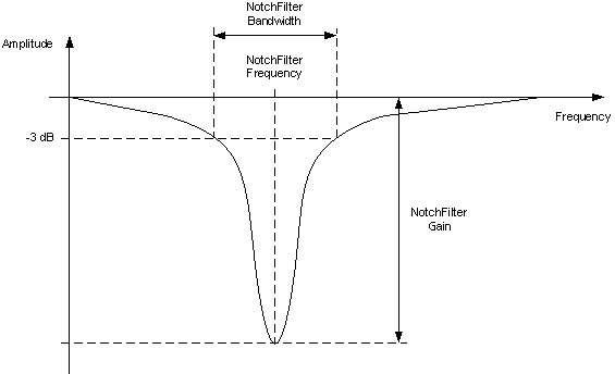
Notch filter: It is a filter that dampens signals only at a specific frequency.
- Harmonic Number: Allows the filter to target specific harmonics of the main frequency.
-
Main Frequency: Main frequency (Hz) at which the notch filter reaches its maximum damping.
Warning
When a user variable is used to set this frequency, it must be initialized to a value other than 0, otherwise a PDI error will occur.
-
Bandwidth: Design parameter. There is a damping of at least 3 dB within the bandwidth. The main frequency at which the maximum damping (notch gain) is reached, lies in the center of this spectrum.
-
Notch gain: Design parameter. This parameters sets the maximum damping (dB) for the main frequency.
Note
Setting this parameter to zero disables the filter.
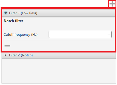
Filter - Low Pass - Cutoff Frequency (Hz): Defines the center frequency where the filter is applied.
-
Sensor filter: Enables a low pass filter which its cutoff frequency is configured manually, allowing the user to input any desired value in Hz.
It is a software filter.
© 2026 Embention. All rights reserved.