Stick
Joystick 16CH
Joystick 16CH is a joystick with 16 channels which sends command signals through radio frequency and CAN bus.
Joystick 16CH can be connected to a control station PCS via CAN bus. This electrical connection is explained in the Hardware Installation section of Joystick 16CH Hardware Manual.
If a Joystick 16CH is connected to a PCS, it will be required to configure the Veronte Autopilot 1x inside the PCS. This configuration is already built and accessible to users as a template in this app.
-
To download it, click on the Import PDI from repo button, then select the PCS CAN Joystick template and finally click on Import.
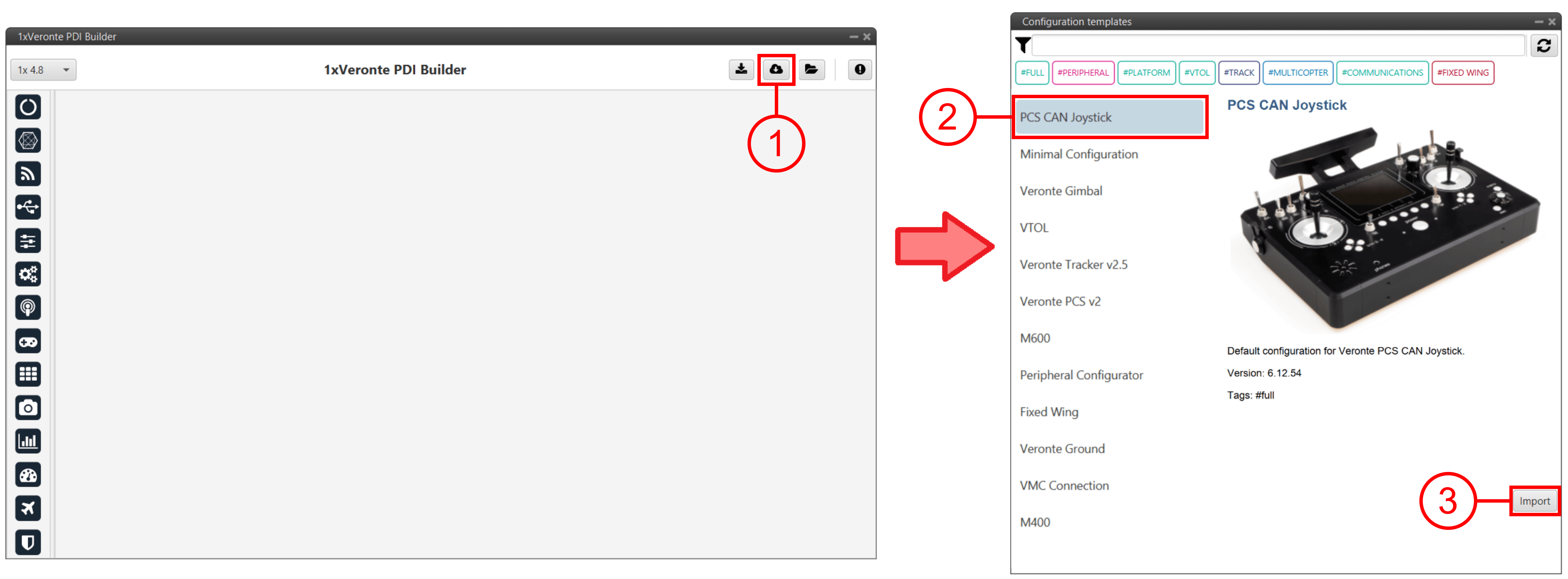
Joystick 16CH - Download template Important
Joystick 16CH has an internal MEX which manages the CAN bus.
Therefore, to communicate Joystick 16CH with the 1x of PCS, its address has to be specified in the 1x configuration.
Since this is a template, for standard operation, users only need to change the MEX address.
CAN Joystick configuration
-
Autopilot 1x has to be configured with a Virtual Stick as it receives signals via CAN bus (not PPM as usual).
- This must be enabled in the Stick menu Virtual Stick panel Input Variable tab with the following configuration:
- Input variables selected from Stick Input r0 to Stick Input r15.
- Update period set to 0.02 seconds.
- Stick Not Detected bit as the Stick ok bit.
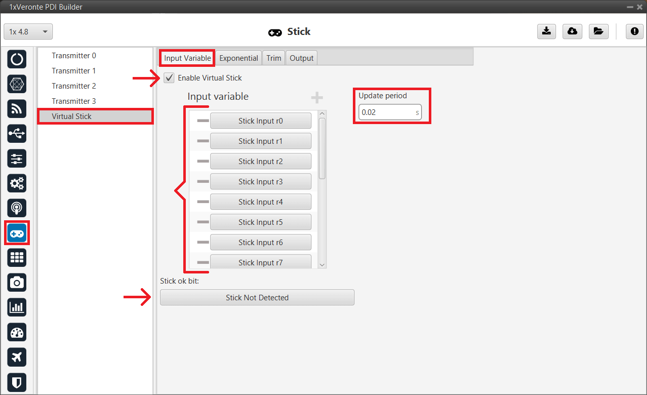
Joystick 16CH - Input Variable configuration -
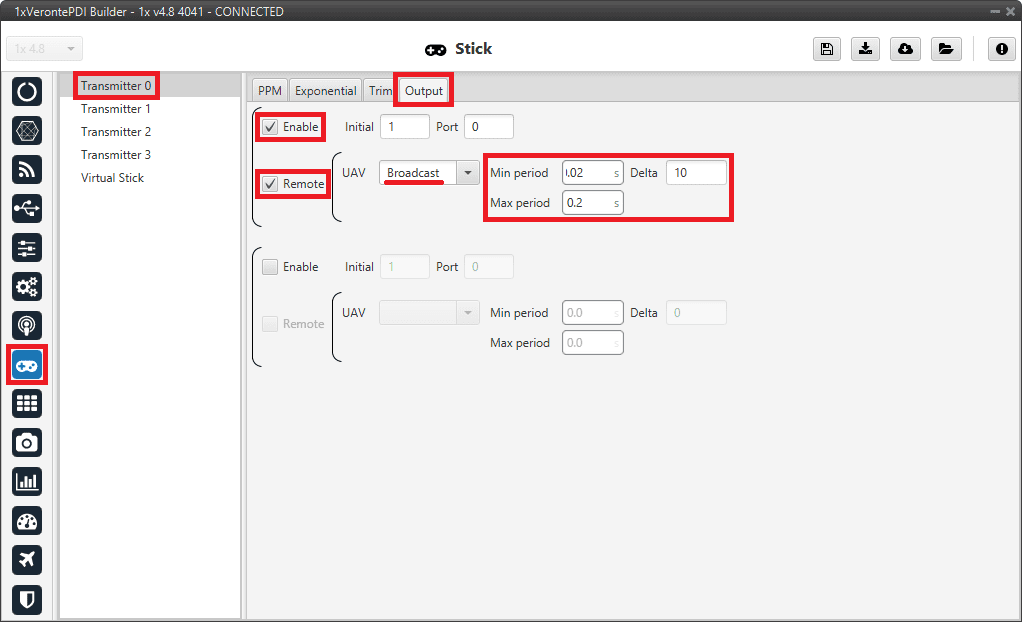
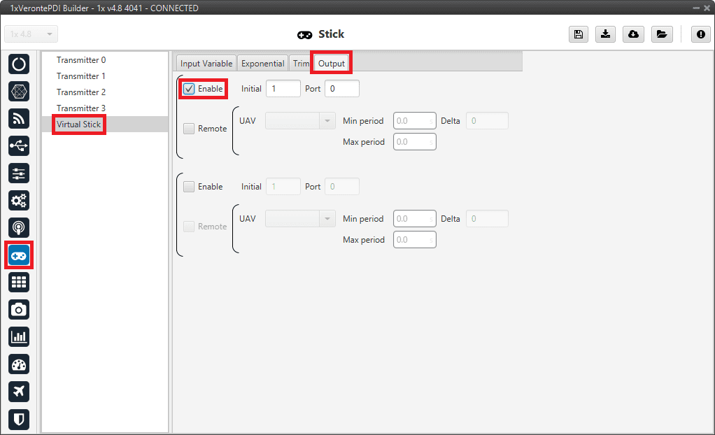
In addition, the Output tab is configured as follows:
- Enable: checked.
- Initial: 1.
- Port: 0.
- Remote: checked.
- UAV: Broadcast.
- Min period: 0.025 s.
- Max period: 0.2 s.
- Delta: 10.
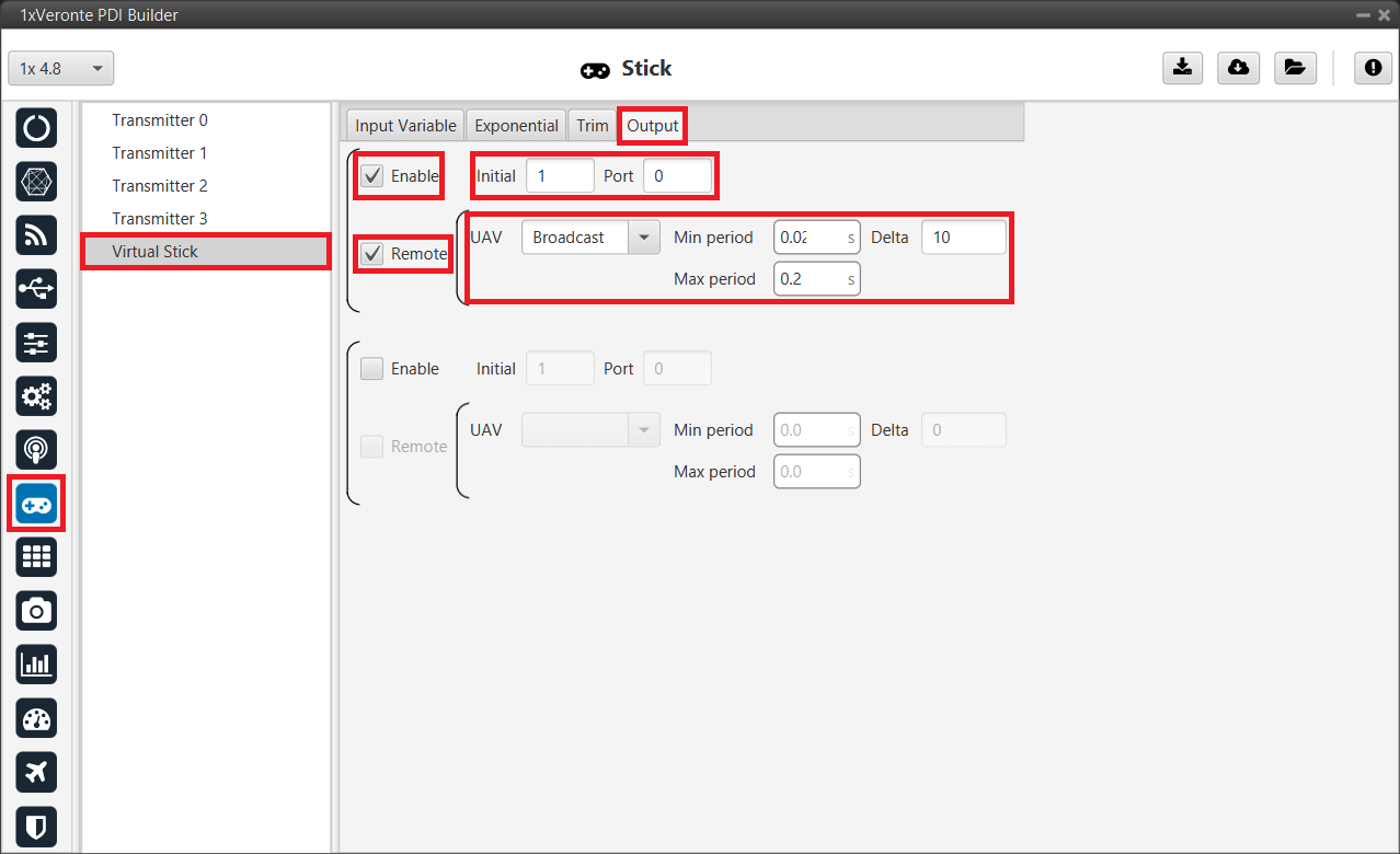
Joystick 16CH - Output configuration
- This must be enabled in the Stick menu Virtual Stick panel Input Variable tab with the following configuration:
I/O Connections
-
In Input/Output menu CAN Setup panel Configuration tab.
An Input filter producer is connected to a CAN to serial consumer. In this example, Input filter 0 is connected to CAN to serial 0.
In addition, this Input filter is configured to take data from Port CAN B, with Id 1301, Mask 2047 and Standard as Filter type.
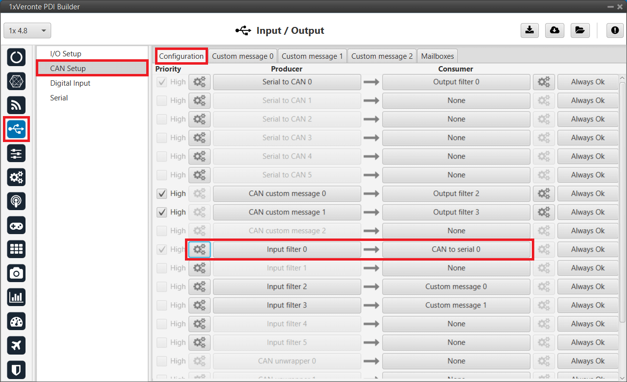
Joystick 16CH - CAN Setup configuration 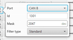
Joystick 16CH - Input filter configuration -
In the I/O Setup panel, a CAN to serial producer is connected to a Commgr Port consumer, and a Commgr port producer is linked to a Serial to CAN consumer.
In this example, CAN to serial 0 producer is connected to Commgr port 4 consumer, and Commgr port 4 producer is linked to Serial to CAN 0 consumer.
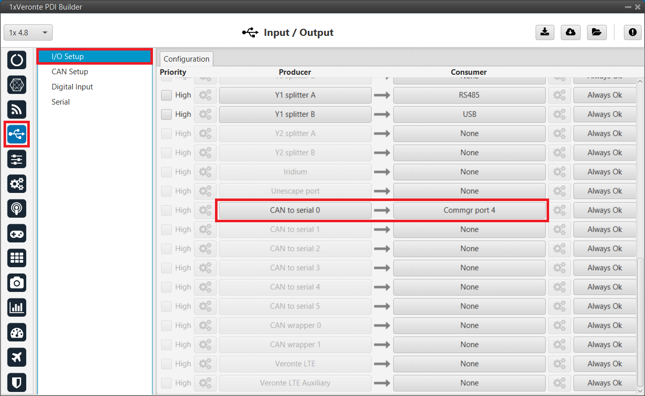
Joystick 16CH - I/O Setup configuration: CAN to serial 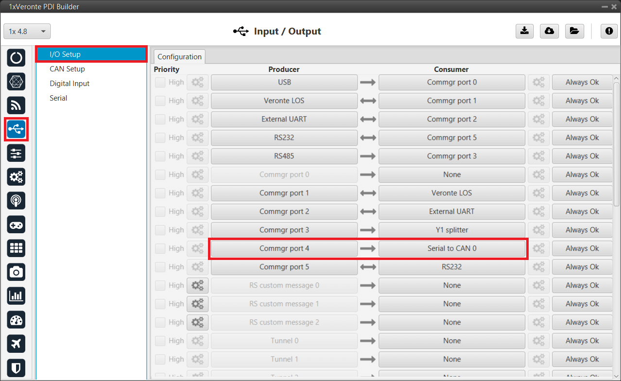
Joystick 16CH - I/O Setup configuration: Serial to CAN -
To properly receive CAN messages from Joystick 16CH, it is necessary to configure some mailboxes on the CAN B port.
In the Input/Output menu CAN Setup panel Mailboxes tab, add at least 4 mailboxes on CAN B with ID 1301.
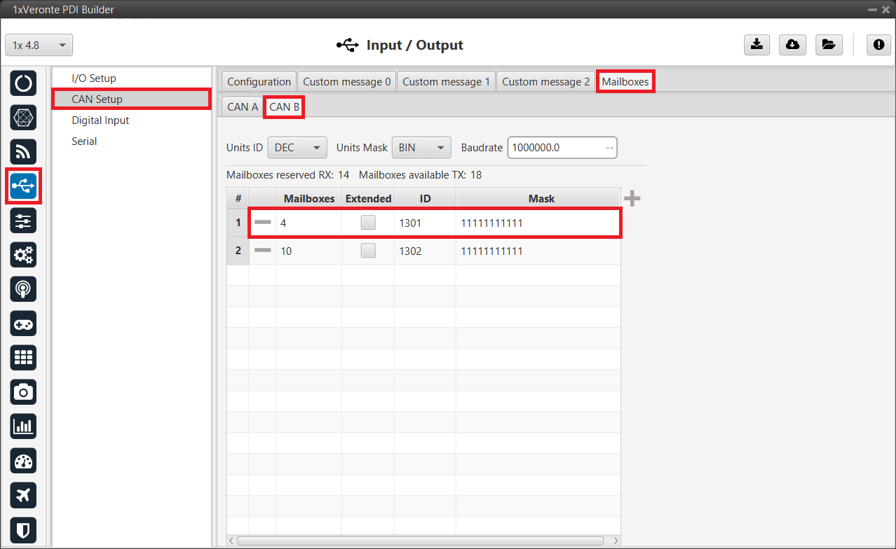
Joystick 16CH - Mailboxes configuration
MEX address configuration
MEX address is configured in the Stick block; this block is usually in a program named Stick by users. To access, go to Block Programs menu and click on Launch Editor.
-
Go to the program where the Stick block is located.
Note
Normally the user has a Stick Program where the blocks that are related to the stick are implemented, however, the name of the user's program may be different.
-
Double-click on the Stick block to access its configuration.
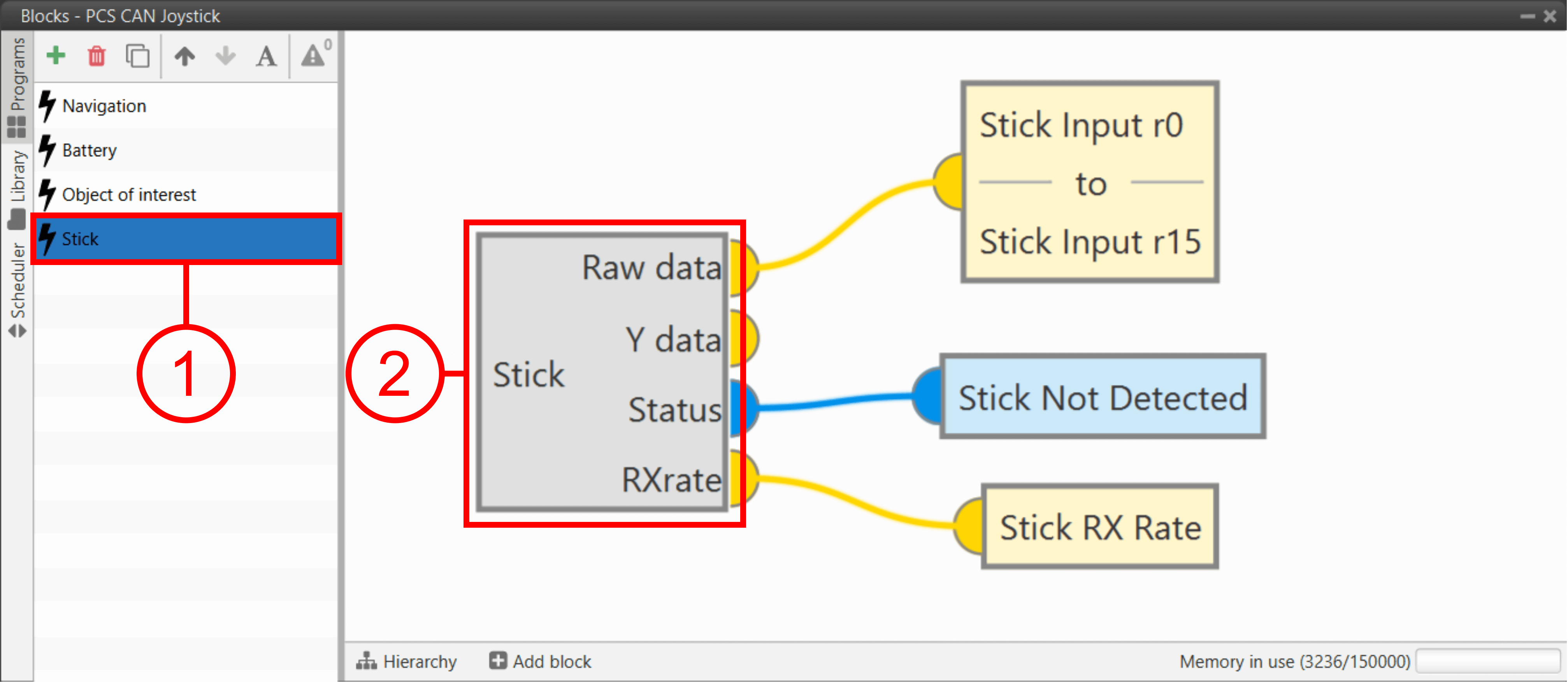
Joystick 16CH - Stick block -
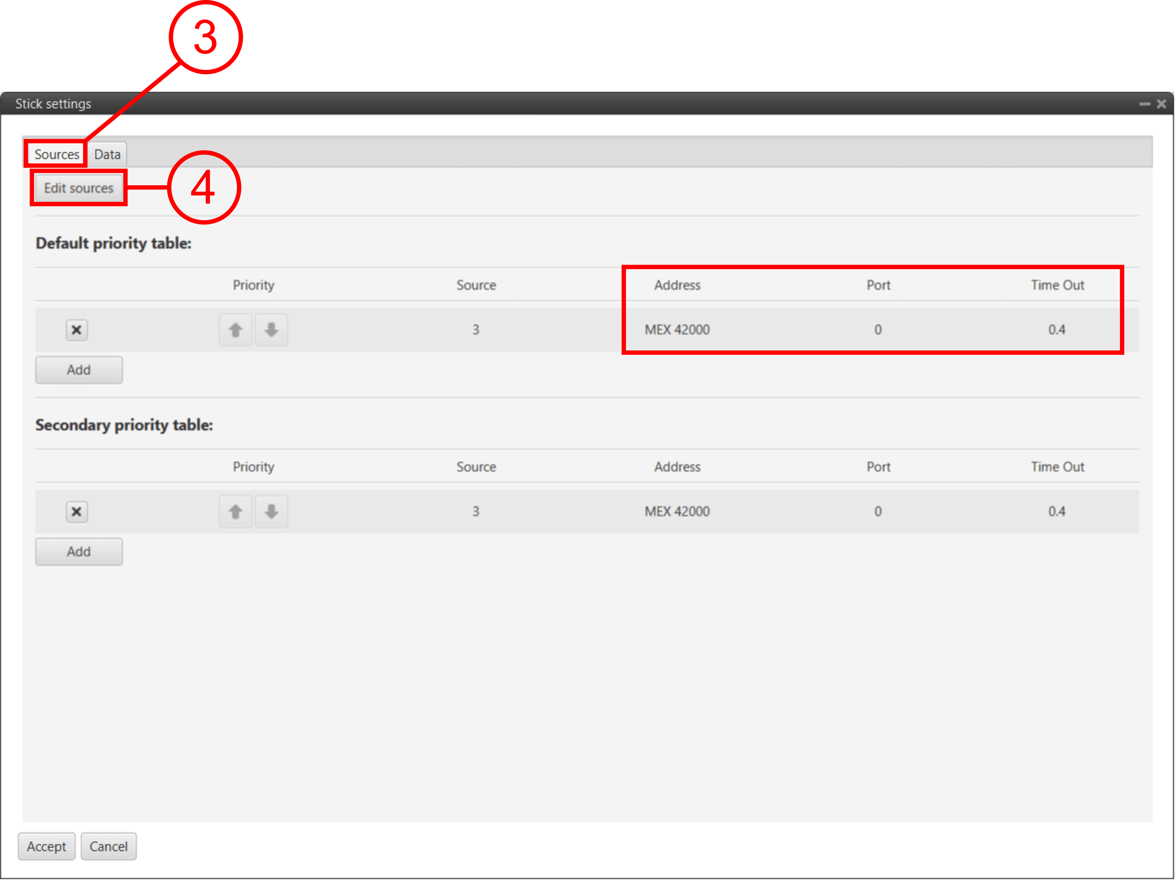
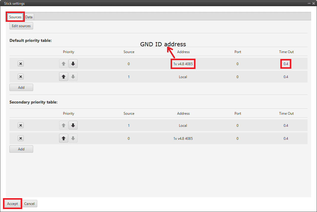
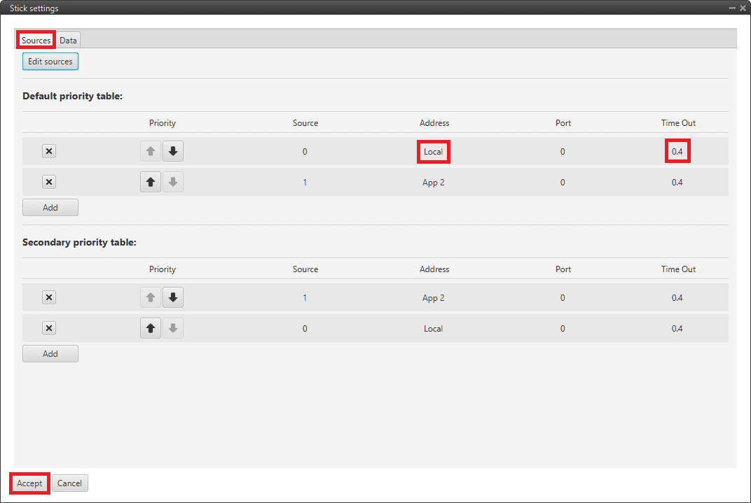
Go to the Sources tab in the new window.
-
Click on the Edit Sources button and:
- Change the address by the one of the MEX installed on the Joystick 16CH, to receive the stick information from that source.
- Select the port previously chosen (0 by default).
- A Time Out of 0.4 s is recommended, which is already set by default.
Joystick 16CH - Stick block settings
Then, if all is correct, users can check that 'Stick not detected' variable will be true.

And that means that the communication is correctly configured.
PPM Stick
General case
This is the case where the 1x ground unit (or PCS) sends commands directly to the 1x air unit.
Follow the steps below to perform a correct stick configuration on both units.
Ground unit
-
Go to Input/Output menu Digital Input panel.
Make sure that the following parameters have been configured:
-
Producer: CAP 0
- Enabled
- Select the pin to which the transmitter is connected (normally EQEP_A)
- Edge detection: First rising edge
-
Consumer: PPM 0
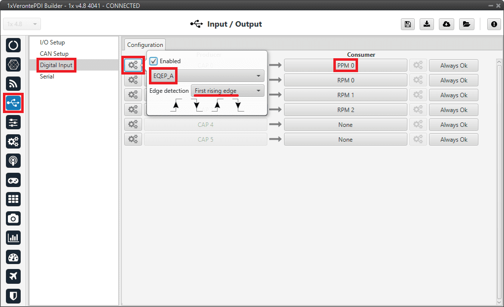
General case (Ground unit) - Digital Input configuration -
-
Go to Connections menu GPIO panel.
Verify that the pin to which the transmitter is connected, in this case GPIO 16 (i.e., EQEP A), is set as input.
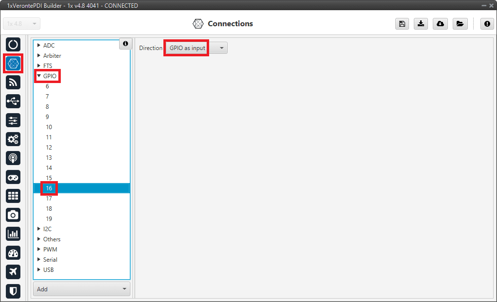
General case (Ground unit) - GPIO configuration -
Go to Stick menu Transmitter 0 panel PPM tab.
Note
Transmitter 0 is configured since the consumer PPM 0 has been chosen in the Digital Input panel.
Select the brand of transmitter that applies.
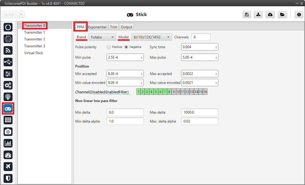
General case (Ground unit) - PPM configuration Note
Jeti 12CH
To integrate the JETI 12 channel model:
- In transmitter brand, select the Jeti option
- Set the Channels to 12
- Disabled the channels 13 to 16
Once the number of channels has been configured, the Brand category will change to Custom, but will retain the Jeti specific configuration.
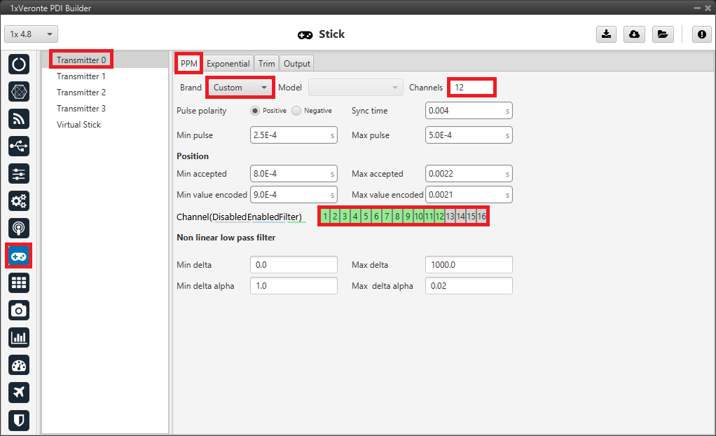
Jeti 12CH - PPM configuration -
Go to Stick menu Transmitter 0 panel Output tab.
Click on Enable and on Remote to send the stick information to the air unit. Please check the recommended values for the configurable parameters described in the Ouput - Stick section of this manual.
General case (Ground unit) - Output configuration
If all these settings are correct, users can check that 'Stick PPM 0 not detected' variable of the GND unit will be true.

Air unit
-
Go to Stick menu Transmitter 0 panel PPM tab.
Select the brand of transmitter that applies (make the same configuration as the ground unit).
-
Go to Stick menu Transmitter 0 panel Output tab.
Just click on Enable.
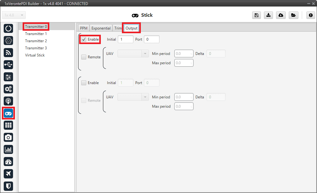
General case (Air unit) - Output configuration -
Go to Block Programs menu Stick program Double click on the Stick block Edit sources.
Note
Normally the user has a Stick Program where the blocks that are related to the stick are implemented, however, the name of the user's program may be different.
Input the ground unit address to receive the stick information from that source and put it as the highest priority in the priority table. We recommend a Time Out of 0.4 s.
General case (Air unit) - Stick block configuration
Then, if all is correct, users can check that 'Stick not detected' variable of the AIR unit will be true.
And that means that the communication between the GND and the AIR unit is correctly configured.
Simulation case (HIL)
In this case, the user is only using one Autopilot 1x.
So users will have to follow steps 1, 2 and 3 explained above for the ground unit, but also steps 2 and 3 of the air unit configuration. However, instead of entering the ground unit address, select the Local option.
On-board PPM receiver case
In this case, follow the steps below to configure the 1x air unit:
-
Go to Input/Output menu Digital Input panel.
Make sure that the following parameters have been configured:
-
Producer: CAP 0
- Enabled
- Select the pin to which the transmitter is connected (normally EQEP_A)
- Edge detection: First rising edge
-
Consumer: PPM 0
On-board PPM receiver case - Digital Input configuration -
-
Go to Connections menu GPIO panel.
Verify that the pin to which the transmitter is connected, in this case GPIO 16 (i.e., EQEP A), is set as input.
On-board PPM receiver case - GPIO configuration -
Go to Stick menu Transmitter 0 panel PPM tab.
Note
Transmitter 0 is configured since the consumer PPM 0 has been chosen in the Digital Input panel.
Select the brand of transmitter that applies.
On-board PPM receiver case - PPM configuration Note
Jeti 12CH
To integrate the JETI 12 channel model:
- In transmitter brand, select the Jeti option
- Set the Channels to 12
- Disabled the channels 13 to 16
Once the number of channels has been configured, the Brand category will change to Custom, but will retain the Jeti specific configuration.
Jeti 12CH - PPM configuration -
Go to Stick menu Transmitter 0 panel Output tab.
Just click on Enable.
On-board PPM receiver case - Output configuration
If all these settings are correct, users can check that 'Stick PPM 0 not detected' variable of the AIR unit will be true.
-
Go to Block Programs menu Stick program Double click on the Stick block Edit sources.
Note
Normally the user has a Stick Program where the blocks that are related to the stick are implemented, however, the name of the user's program may be different.
Input the address as Local to receive the stick information from that source and put it as the highest priority in the priority table. We recommend a Time Out of 0.4 s.

On-board PPM receiver case - Stick block configuration
Then, if all is correct, users can check that 'Stick not detected' variable of the AIR unit will be true.
And that means that the communication with the AIR unit is correctly configured.
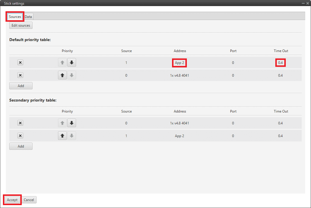
Stick widget
To configure the Stick widget of Veronte Ops as a control input of 1x, follow the next steps:
-
Go to Block Programs menu Stick program Double click on the Stick block Edit sources.
Note
Normally the user has a Stick Program where the blocks that are related to the stick are implemented, however, the name of the user's program may be different.
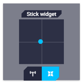
Add a source with Address 2 (App 2) to receive the stick information from the stick widget (of Veronte Ops) and put it as the highest priority in the priority table. A Time Out of 0.4 s is recommended.
Stick block - Stick settings -
Configure the Stick Widget in Veronte Ops. Please find an example of how to configure it in the Stick widget - Integration examples section of the Veronte Ops user manual.
USB joystick
Veronte software is able to detect USB devices such as joystick. The signals of these devices can be read and configured to send stick information to Veronte Autopilot 1x through the Stick widget of Veronte Ops.
To configure them:
- Connect the USB joystick to the computer.
-
Go to Block Programs menu Stick program Double click on the Stick block Edit sources.
Note
Normally the user has a Stick Program where the blocks that are related to the stick are implemented, however, the name of the user's program may be different.
Add a source with Address 2 (App 2) to receive the stick information from the stick widget (of Veronte Ops) and put it as the highest priority in the priority table. A Time Out of 0.4 s is recommended.
Stick block - Stick settings -
In Veronte Ops, configure the Stick Widget to be used with a USB joystick. Please find an example of how to configure it in the USB joystick - Integration examples section of the Veronte Ops user manual.
Note
It is also possible to convert USB joystick commands into PPM signals using the Veronte Stick Expander.
For more information about this product, please visit the Stick Hardware Manual or contact sales@embention.com.
Virtual Stick
It is necessary to configure a Virtual Stick to process the stick information received from sources other than PPM or USB (by CAN, Serial, ADC, etc.). This stick data must be stored in user variables, and once the virtual stick is configured, these will be processed as stick control signals.
To configure a virtual stick, follow the next steps:
-
Go to Stick menu Virtual Stick panel Input Variable tab.
- Enable the virtual stick
- Enter an update period (0.02 s is recommended).
- Add the variables containing the stick information in Input Variable field.
- Select as Stick ok bit a user bit variable to indicate if the Virtual Stick configuration has been properly set.
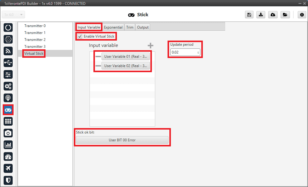
Virtual Stick - Input Variable configuration -
Go to Stick menu Virtual Stick panel Output tab.
Just click on Enable.
Virtual Stick - Output configuration Note
If all these settings are correct, users can check the variable previously set as Stick ok bit is true.
-
Go to Block Programs menu Stick program Double click on the Stick block Edit sources.
Note
Normally the user has a Stick Program where the blocks that are related to the stick are implemented, however, the name of the user's program may be different.
Add a source with address Local to receive the stick information from the configured variables and put it as the highest priority in the priority table. A Time Out of 0.4 s is recommended.
Virtual Stick - Stick block configuration Then, if all is correct, users can check that Stick not detected variable is true, which means that the communication is correctly configured.
© 2026 Embention. All rights reserved.