RPM Sensors
This section defines a general explanation of how to integrate RPM sensors with Autopilot 1x.
Once the device hardware installation explained in the RPM Sensors - Integration examples section of the 1x Hardware Manual has been completed, follow the steps below to perform the proper software installation.
-
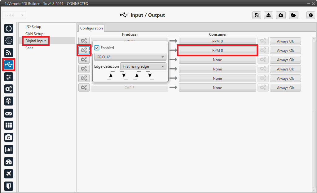
Go to Input/Output menu Digital Input panel.
Connect any CAP producer to a RPM consumer, in this example:
-
Producer: CAP 1
- Enabled
- Select the pin to which the RPM sensor is connected.
- Edge detection: Select the desired detection option.
-
Consumer: RPM 0

RPM Sensors - Digital Input configuration -
-
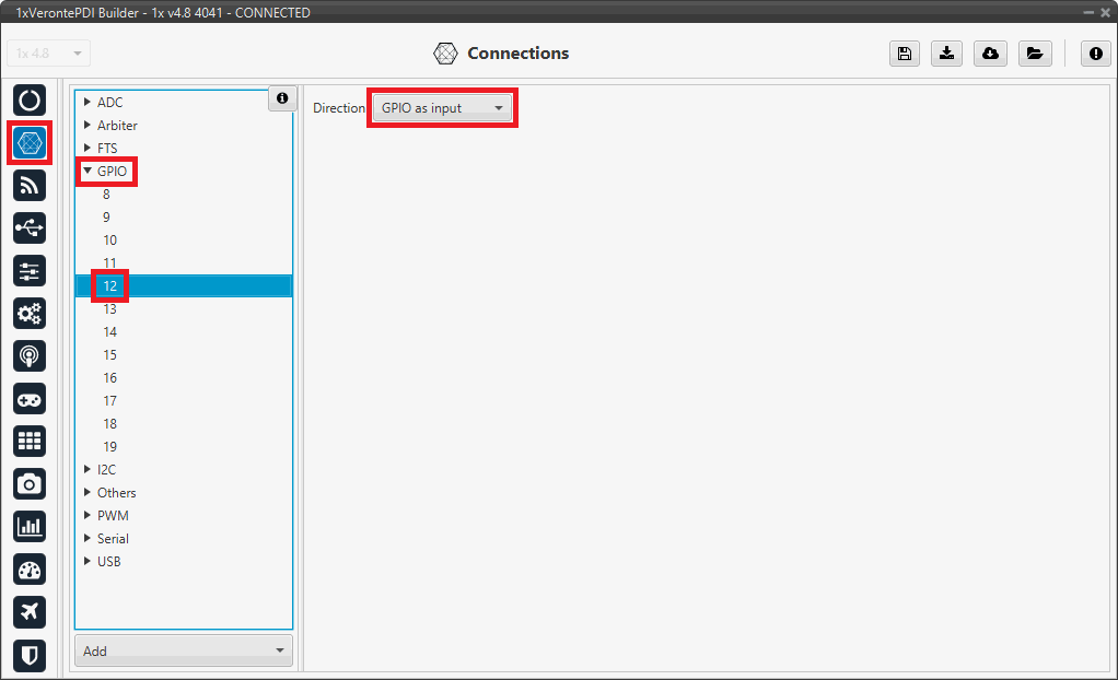
Go to Connections menu GPIO panel.
Verify that the pin to which the RPM sensor is connected, in this case GPIO 12, is set as input.

RPM Sensors - GPIO configuration -
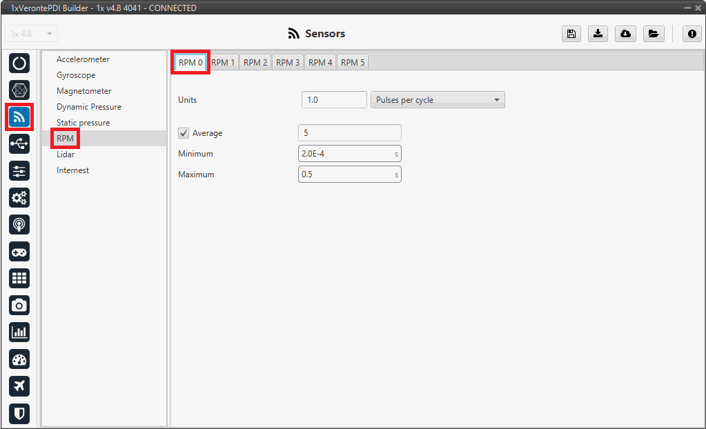
Go to Sensors menu RPM panel RPM 0 tab (since the consumer RPM 0 has been chosen).
Set the configuration parameters according to the user's specific RPM sensor characteristics and requirements:

RPM Sensors - RPM configuration For more information about this panel, visit the RPM - Sensors section of the 1x PDI Builder user manual.
In addition, users can monitor the sensor signal reading in the corresponding real variable (RPM X), in this case this variable is RPM 0.
© 2025 Embention. All rights reserved.