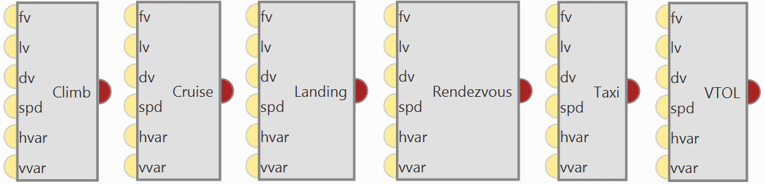
Guidance blocks
When defining a guidance system, we refer to a set of commands sent to the platform controller in order to make it carry out a certain task. This task could be follow a line, climb, land, hold one of its states at a certain value and so on.
In 1x PDI Builder, it is possible to combine a series of guidances to create custom flight phases that will make the aircraft perform in a given way.
Each Guidance block contains a set of parameters to be configured. All of them are presented as follows.
| Name | Description |
|---|---|
| Climb | Makes the aircraft climb from the start of the phase to another altitude. |
| Cruise | Makes the aircraft follow a determined route created by the user. |
| Landing | Creates the route that the airplane will follow to land. |
| Rendezvous | Used to create a meeting point where the Air unit will approach a second unit (either Air or Ground) within a determined offset. |
| Taxi | Creates a linear path along the runway that is followed by the aircraft. |
| VTOL | Vertical take-off and landing. |
| Yaw current/heading/north | Indicates the behavior of the platform in the yaw axis. |
Guidance blocks common configuration
All the guidance blocks presented below, have the same inputs and outputs, and some common configuration parameters.
-
Inputs
 (Optional) fv: First component of desired 'hover here' arcade velocity in the horizontal plane.
The actual direction of this speed depends on the selected arcade axis. (Optional) lv: Second component of desired 'hover here' arcade velocity in the horizontal plane.
The actual direction of this speed depends on the selected arcade axis. (Optional) dv: Down (vertical) 'hover here' desired arcade velocity. (Optional) spd: Arcade cruise speed increment. (Optional) hvar: Scale variable for the T-Sched PID of the horizontal guidance. (Optional) vvar: Scale variable for the T-Sched PID of the vertical guidance.
(Optional) fv: First component of desired 'hover here' arcade velocity in the horizontal plane.
The actual direction of this speed depends on the selected arcade axis. (Optional) lv: Second component of desired 'hover here' arcade velocity in the horizontal plane.
The actual direction of this speed depends on the selected arcade axis. (Optional) dv: Down (vertical) 'hover here' desired arcade velocity. (Optional) spd: Arcade cruise speed increment. (Optional) hvar: Scale variable for the T-Sched PID of the horizontal guidance. (Optional) vvar: Scale variable for the T-Sched PID of the vertical guidance. -
Output
 Pin 0: Guidance data for the Guidance Computation block.
Warning
To produce a guidance computation, these blocks must be connected to the Guidance Computation block via this output.
-
Configuration menu:

Common guidance blocks configuration All the parameters that define the guidance are detailed:
- Patch: This option allows the user to select the first path to be flown by the aircraft. The user should first enable this option and then select the desired path to bo the first-of-the-route.
-
Set height mode: Height mode indicates how the aircraft will perform the defined path. There are three possible height modes:
- 2D mode: If this mode it is selected, the platform will follow the predifined route without taking into account the altitude of the waypoints, it will keep the altitude that it has at the moment it enters in the guidance.
-
2.5D mode: The vehicle will follow a 3D trajectory that connects both waypoints. However, it will give priority to horizontal guidance.
Autopilot 1x will try to adjust its position and altitude to the path (both horizontally and vertically), but if for any reason it cannot reach the altitude of the final waypoint, it will considered that it has been reached if its position matches the position of the waypoint.
-
3D mode: The vehicle will follow a 3D trajectory that connects both waypoints. In this case, horizontal and vertical guidance have the same priority level. This means that Autopilot 1x will not consider that a waypoint has been reached until its position and altitude match the waypoint's ones.
As this type of guidance may result in a vertical flight, it is reserved for multicopters or hybrid platforms.
-
Arcade position/speed transition: In Arcade mode the trajectory generated (position) is not followed and instead the aircraft moves according to the commanded speed.
The Horizontal and Vertical speed parameters serve as the upper thresholds for when the aircraft guidance should be based on position, even in Arcade mode. This parameters are mainly useful for platforms like multicopters.
-
Set speed: This option sets the speed that the vehicle will have during the manoeuvre.
- Cruise: Lets the user set the velocity modulus of the guidance. This velocity can be slightly modified by the autopilot control algorithms.
- Waypoint: If enable, it indicates the speed at which the platform will reach the waypoints of the path, i.e. it will travel along the path with the speed indicated in the option Cruise and then it will decelerate or accelerate to the speed indicated here.
- Type: Defined speed. Can be IAS (Indicated Airspeed) or Ground speed. Normally, IAS is used for airplanes and Ground speed for multicopters.
- Deceleration: This can only be configured when Waypoint option is enabled. Maximum allowed acceleration/deceleration to meet the desired velocity.
-
Guidance control: These PIDs are defined to guarantee stability of guidance loop, they are used to calculate the Desired Speed Vector based on the current position error.
Then, the resulting vector, along with the Guidance parameters, will be used to generate the Desired variables (ID 100 - 258 Rvars) that can be used as inputs for the control loops.
For both Horizontal and Vertical guidance, the user can choose the type of control between PID or T-Sched PID.
Besides, by clicking on the
 icon of both guidance, a pop-up window will appear where the control parameters should be entered, for more information on the latter check Control blocks.
In the horizontal-position PID (see image below), North-East current position of the aircraft is compared to the desired position. The output of the PID controller is going to be a ground speed in the North-East plane, which translates into a desired lateral and front ground speeds in body axes. The same logic applies for the vertical-position PID.

Horizontal Position PID However, the algorithm is more complex than this simple PID.
For tuning, it is usual to use only proportional term in the PID:
- A high proportional will converge faster to the desired position but with overshoot.
- A lower proportional will make the arrival to the desired position slower but it is a smooth convergence.
Next figures shows this behavior with and .


PID Proportional gains
Guidance-generated Variables
The guidances contained within Veronte Autopilot 1x generate a series of variables that are later used in the control loops as the input of the PIDs. Generally, variables named as Desired are used in this Guidance.
The list of variables is the following:
- Desired position.
- Track position.
- Track state (current patch, last patch).
- Desired latitude, desired longitude, desired WGS84, desired MSL, desired AGL.
- Desired velocity.
- Desired front groundspeed, desired lateral groundspeed, desired velocity down.
- Desired tangential acceleration.
- Desired IAS.
- Guidance north error.
- Guidance east error.
- Guidance down error.
- Desired body velocities.
- Desired velocities north, east, down.
- Desired heading, FPA and bank.
- Route-guidance distance - tangential component.
- Route-guidance distance - horizontal component.
- Route-guidance distance - perpendicular component.
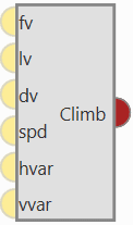
Climb
Climb guidance is used to make the aircraft climb from the start of the phase to another altitude. Commonly, this guidance is used after the take-off to fly from the ground to cruise altitude through a loiter point, but it can be employed for other purposes.
Climbing guidance generates a three-dimensional trajectory.
Warning
In order to produce a guidance computation this block has to be connected to the Guidance Computation block.
-
Configuration menu:
The climbing path is automatically generated and is not directly shown to the user until the aircraft enters this phase. This is due to the algorithm recalculating the path each time to take into account the aircraft's actual flight conditions and the user's indicated parameters.

Climb block configuration Below, the parameters shown above are going to be described. Later, a brief description of the algorithm and its behavior in different possible situations will be presented:
-
Patch: This is detailed in the common guidance block parameters, described at the beginning of this section in Guidance blocks common configuration.
-
Set height mode: This is detailed in the common guidance block parameters, described at the beginning of this section in Guidance blocks common configuration.
-
Arcade position/speed transition: This is detailed in the common guidance block parameters, described at the beginning of this section in Guidance blocks common configuration.
-
Set speed: This is detailed in the common guidance block parameters, described at the beginning of this section in Guidance blocks common configuration.
-
Guidance control: This is detailed in the common guidance block parameters, described at the beginning of this section in Guidance blocks common configuration.
-
Runway and Loiter position: Here the user can define the loiter and runway positions and direction. However, the default option is to define them in the Runway option of Veronte Ops (for more information, see Veronte Ops manual).
If the Advanced option is chosen, then the user can define these parameters. By clicking on
 or
or  different options will be displayed:

Runway and Loiter Position Options -
Loiter point: Defines the loiter point. The two available options are:
-
icon selected: By default, this point is the runway's loiter.
But the user can select in the drop-down list any other previously defined point.
This includes waypoints defined in the Mission (in Veronte Ops), among many others.
-
icon selected: Alternately, the user can manually define the Loiter point. Then it can be configured in two ways:
- Relative: In this case, the position of the point is relative to another point. That point could be any platform fitted with an Autopilot 1x.
- Absolute: The coordinates can be set in UTM, MGRS, Decimal Degrees or Degress º " '. They are indicated through the latitude, longitude and altitude (being possible to define this last one with respect to the ellipsoid, WGS84, to the sea level, MSL or to the ground, AGL).
-
-
Direction: Defines the runway direction. Again, there are two available options:
-
icon selected: By default, it is the same as the selected runway.
It can be also chosen from a list of options including runway direction, tailwind direction, etc.
-
icon selected: Alternately, it can also be defined as an angle with respect to the magnetic north.
-
-
Loiter pos is center: If this box is enabled, the defined loiter point will be the center of the loiter circular trajectory. In case of not, the circular loiter trajectory will pass through that point.

Climb route top and front views with parameter identification -
-
Route: Here is where the user can set some of the the climbing path parameters (those highlighted in red on the above diagram).
First, the user-defined parameters are described and then, some considerations on the behavior of the climb algorithm are explained:
- Taxi extension: This parameter does not apply to this algorithm.
-
Horizontal extension (dxy): Absolute ground distance of the first path, . From the start of the climb to the start of the turn that faces the loiter path. This distance will remain fix always and it will also fix path's final point height, . More information below.
-
Radius Head Turn (R3): Radius of the turn to head the platform towards the loiter.
- Radius loiter (R1): Radius of the ascending helix path to reach the loiter height.
- Flight Path Angle: The () is the angle at which the aircraft will climb. Before the algorithm execution, all Flight Path Angles, , are equal: . The algorithm can modify and . In that case, the Flight Path Angle option will serve as the upper threshold.
Note
The rest of the parameters shown in the figure above are calculated automatically by the algorithm ().
Each of these parameters can be entered manually or linked to an Operation Guidance defined by the user clicking on
or .
-
Climbing guidance parameters behavior
The climbing track is not fix, the algorithm recalculates the paths each time to take into account the aircraft position and the user's parameters. The trajectory usually has 4 paths, excluding the final loiter path:
-
General trajectory description:
-
is the first path. The user can set the horizontal length, , the direction (in Runway direction) and the path's final point height, with the defined Flight Path Angle. This is very relevant, as seen later. The path length can not be zero.
-
: Circular turn to head the platform towards the loiter. The user can set the radius, . It is possible to set this path to zero clicking on
.The FPA, , can be modified by the algorithm.
-
: Straight path that reaches the climbing loiter point. This path is completely automatic generated. Its FPA, , can be modified by the algorithm.
- : Ascending helix path to reach the loiter height. The user can set the radius, .
-
-
Loiter height effect: Loiter height's, , modifies the algorithm general behavior. Depending on whether is bigger or smaller than or smaller than the algorithm will modify some parameters, in particular the flight path angles:
-
: This is the general case, in this situation no corrections will be applied as shown below and .

Climbing heights when H2 < Hc -
: In this case, the algorithm will compute a new to avoid surpassing the loiter's height and will be zero.

Climbing heights when H4 < Hc < H2 -
: In this case, the algorithm will force . So will be the new loiter height keeping and the other flight paths angles equal to zero, .

Climbing heights when Hc < H4
-
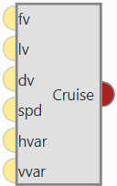
Cruise
This phase is used to make the aircraft follow a position-based route created by the user in Veronte Ops (for more information, see Veronte Ops manual). This is the principal use of this guidance algorithm, but it can also be used to make the aircraft go to a certain location (e.g, a waypoint) without indicating the complete route, thus being a guidance used to command a movement by position.
Cruise guidance generates a three-dimensional trajectory.
Warning
In order to produce a guidance computation this block has to be connected to the Guidance Computation block.
-
Configuration menu:
Cruise block configuration All the parameters that define the cruise guidance are detailed.
-
Patch: This is detailed in the common guidance block parameters, described at the beginning of this section in Guidance blocks common configuration.
-
Set height mode: This is detailed in the common guidance block parameters, described at the beginning of this section in Guidance blocks common configuration.
-
Arcade position/speed transition: This is detailed in the common guidance block parameters, described at the beginning of this section in Guidance blocks common configuration.
-
Set speed: This is detailed in the common guidance block parameters, described at the beginning of this section in Guidance blocks common configuration.
-
Guidance control: This is detailed in the common guidance block parameters, described at the beginning of this section in Guidance blocks common configuration.
-
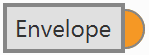
Envelope
Envelope block is used to configure the flight envelope of the aircraft. Here the limits that will not be exceeded during the operation are set.
These limits are respected by the guidance and depend on how the control is implemented.
Warning
Although the acceleration has been limited here, if the control is configured so that the pilot in manual mode can control the pitch angle, this acceleration limit will have no effect.
Warning
In order to produce a guidance computation this block has to be connected to the Guidance Computation block.
-
Output
 Pin 0: Flight envelope configuration.
Important
If users wish to have more than one envelope in their configuration, they must configure as many envelope blocks as they wish and make the connection to the Guidance Computation block through a block of type Switch.
To do this, the desired conditions must be set for the Autopilot 1x to make the switch in the Switch block.
An example of how to implement more than one envelope is shown below:

-
Configuration menu: The configuration of this block is divided into 3 different tabs:
Envelope

Envelope block configuration - Envelope - VTOL: If this option is enabled, when the vehicle reaches the last waypoint of its route (and it is an open path), a hover is done instead of a loiter point.
-
Airspeed Limits: Limits for the indicated airspeed (IAS). Values indicated here have effect over the "Cruise" guidance, but is overrided if there is a Hold command on the IAS, so the user must be careful with the velocity commands.
-
Ground Speed Limits: Minimum and maximum ground speed of the platform. In case of strong wind, these parameters set the minimum GS that the aircraft can reach, for lower values than this one the thrust will be automatically increased to gain speed and avoid a point where the platform is stopped in the air.
-
Vertical Speed Limits: Similar to the previous limit. It sets the minimum and maximun value for the vertical speed of the platform.
- Flight Path Limits: Maximum and minimum values for the flight path angle (angle of climb or descent).
Note
- Users can manually enter values or select variables instead.
- These limits will modify how guidances command your vehicle to move, but will not apply when the aircraft is not being controlled by a guidance (i.e manual/assisted flight).
- These values should not represent the maximum limits that the platform can withstand, but the maximum values that should be present during a normal operation.
Acceleration limit
In this second tab there are more options to fix the limits (positive and negative direction) of acceleration and jerk in SI units.
Acceleration limits are applied in any phase with position guidance. They modify the desired velocity. The algorithm compares the current desired velocity with thatstored in previous step. There are six values to define.

Envelope block configuration - Acceleration limit (Spherical frame) The configurable options in this menu are:
- Enable/Disable the acceleration limit.
-
Type: User can choose between Cartesian Body and Spherical.
Cartesian Body is normally used for multicopters or aircraft that allow 3-dimensional movement, while the Spherical type is used for conventional aircraft.
-
Enable/Disable angular rates: The user also can selected directly angular rates option which allows him set limits in Y body rate and Z body rates.
-
Axes:
- In Cartesian Body the axes refer to the body frame (X Body Axis, Y Body Axis, Z Body Axis).
- In Spherical type, the algorithm internally applies limits in module, inclination and azimuth to maintain the limits set by the user in body frame (body frame limits will be turn into spherical limits).
-
Positive direction: The limit for acceleration. If desired velocity has the same sign as in the previous step, and it is lower (in absolute value) this limit is applied. For example, if a multicopter is flying in negative X direction, and it has to increase desired velocity in same direction this limit will be applied.
-
Negative direction: The limit for deceleration. In the case positive direction limit is not used.
The second derivative of velocity (Jerk) imposes another limit in acceleration. It modifies the behavior of the vehicle.
Depending on values, it's possible to get more smoothness during guidance. Algorithm ensures that when desired velocity is reached the acceleration value is near 0. As acceleration limits, user can set 6 values (3 for positive direction limit and 3 for negative direction limit).

Envelope block configuration - Acceleration limit (Cartesian frame) The effects of these limitations are explained below.
First, the acceleration limits are disabled. The stick that controls Thrust is moved and desired velocity change according to this stick command.
In Desired velocity chart we can see this effect and in bottom acceleration chart is shown how acceleration is not limited (hight values reached).

Only velocity limit (Thrust) Now, a limit in acceleration bottom axis is set to 0.1. Now the desired speed grows with a lower slope due to the imposed limitation.
Also in the acceleration bottom chart we can see how the value oscillates within the imposed limit.

Acceleration limit (Thrust) To compare acceleration and jerk, roll axis is chosen. In the first gif below only the first limit is applied.

Acceleration limit (Cartesian frame) When the jerk limit is also enabled we can see how acceleration (in Y Body axis) does not show peaks, and changes in desired velocity are smoother.

Acceleration limit (Cartesian frame) Obstacles/Geofencing
Users should configure this last tab when using the geofencing functionality of Veronte Autopilot 1x.
The maximum deceleration desired when approaching the obstacle can be entered manually or by selecting a variable.

Envelope block configuration - Obstacles/Geofencing
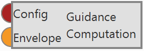
Guidance Computation
Guidance Computation block takes the configuration and arcade data from a given type of guidance and computes the guidance parameters. It is always necessary to add it with these Guidance blocks: Climb, Cruise, Landing, Rendezvous, Taxi and VTOL.
In additon, an Envelope block must also be connected to this block to compute the flight envelope of the aircraft in the guidance.
-
Inputs
Config: Guidance configuration. Envelope: Flight envelope.
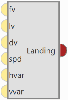
Landing
Landing guidance is used to generate the flying path the aircraft will follow when landing on a certain runway.
Landing guidance generates a three-dimensional trajectory.
Warning
In order to produce a guidance computation this block has to be connected to the Guidance Computation block.
-
Configuration menu:
The generated path is not directly indicated by the user as in cruise guidance (which is defined in Veronte Ops), instead a trajectory is generated based on the parameters detalied later in this section, as in climb guidance.
Below, find all the information to be defined by the user together with the corresponding Figures showing the location of these parameters in the menu.

Landing block configuration -
Patch: This is detailed in the common guidance block parameters, described at the beginning of this section in Guidance blocks common configuration.
-
Set height mode: This is detailed in the common guidance block parameters, described at the beginning of this section in Guidance blocks common configuration.
-
Arcade position/speed transition: This is detailed in the common guidance block parameters, described at the beginning of this section in Guidance blocks common configuration.
-
Set speed: This is detailed in the common guidance block parameters, described at the beginning of this section in Guidance blocks common configuration.
-
Guidance control: This is detailed in the common guidance block parameters, described at the beginning of this section in Guidance blocks common configuration.
-
Runway and Loiter position: Here the user can define the loiter and runway positions and direction. However, the default option is to define them in the Runway option of Veronte Ops (for more information, see Veronte Ops manual).
If the Advanced option is chosen, then the user can define three parameters. By clicking on
or different options will be displayed:

Runway and Loiter Position Options -
Touch point: Defines the touch point of the runway. The user can configure it in 2 different ways:
-
icon selected: By default, this point is the runway's touch point.
But the user can select in the drop-down list any other previously defined point. This includes waypoints defined in the Mission (in Veronte Ops), among many others.
-
icon selected: Alternately, the user can manually define this point. Then it can be configured in two ways:
- Relative: In this case, the position of the point is relative to another point. That point could be any platform fitted with an Autopilot 1x.
- Absolute: The coordinates can be set in UTM, MGRS, Decimal Degrees or Degress º " '. They are indicated through the latitude, longitude and altitude (being possible to define this last one with respect to the ellipsoid, WGS84, to the sea level, MSL or to the ground, AGL).
-
-
Loiter point: Defines the loiter point. The two available options are:
-
icon selected: By default, this point is the runway's loiter.
But the user can select in the drop-down list any other previously defined point.
This includes waypoints defined in the Mission (in Veronte Ops), among many others.
-
icon selected: Alternately, the user can manually define the Loiter point. Then it can be configured in two ways:
- Relative: In this case, the position of the point is relative to another point. That point could be any platform fitted with an Autopilot 1x.
- Absolute: The coordinates can be set in UTM, MGRS, Decimal Degrees or Degress º " '. They are indicated through the latitude, longitude and altitude (being possible to define this last one with respect to the ellipsoid, WGS84, to the sea level, MSL or to the ground, AGL).
-
-
Direction: Defines the runway direction. Again, there are two available options:
-
icon selected: By default, it is the same as the selected runway.
It can be also chosen from a list of options including runway direction, tailwind direction, etc.
-
icon selected: Alternately, it can also be defined as an angle with respect to the magnetic north.
-
-
Loiter pos is center: If this box is enabled, the defined loiter point will be the center of the loiter circular trajectory. In case of not, the circular loiter trajectory will pass through that point.
-
-
Trajectory distances: Here the user defines some of the trajectory distances. This distances match the trajectory patches lengths or are proportional to them. See the explanation below for more information on every patch.
- Taxi extension: Distance from touchdown to where the aircraft is brougth to a full stop.
- Horizontal extension (dxy): Distance before the head of the runway. At the end of this length, touchdown is expected.
- Radius Head Turn (R3): Radius of the last turn in order to face the runway direction ().
- Radius loiter (R1): Radius of the descending loiter for the aircraft to reach an altitude suitable to perform the landing manoeuvre ().
Each of these parameters can be entered manually or linked to an Operation Guidance defined by the user clicking on
or .Note
Some patches don't have an associated user-defined distance, and are automatically calculated by the landing guidance algorithm, as they depend on some of the above distances and other parameters defined below.
-
Trajectory flight path angles: Here the user defines the desired trajectory flight path angles for each of the patches of the trajectory. See the explanation below for more information on every patch.
- Initial maximum (absolute): Desired flight path angle of patch 0.
- Loiter: Desired flight path angle of patch 1.
- Aim: Desired flight path angle of patches 2 and 3.
- DXY: Desired flight path angle of patch 4.
-
Trajectory velocities: Here the user defines the desired trajectory velocities for each of the patches of the trajectory. See the explanation below for more information on every patch.
- Initial: Desired velocity of patch 0.
- Loiter: Desired velocity of patch 1.
- Aim: Desired velocity of patches 2 and 3.
- DXY: Desired velocity of patch 4.
Each of these parameters can be entered manually or linked to an Operation Guidance defined by the user clicking on
or .
-
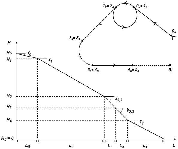
The generated trajectory of the landing guidance defines the route that the aircraft follows from the point when the phase with this guidance is entered, to the point where it touches the ground, see the Figure below. The landing route has two parts, being decomposed into 6 patches:
-
First part: Descending loiter used to descend from the cruise altitude to an altitude where the heading manoeuvre towards the runway can be performed.
-
Patch 0: This patch is generated from the point the landing phase is entered to where the loiter is located. Variables that influence this patch are , altitudes and , and Loiter point position.
-
Patch 1: The patch length () will depend on the amount of loops on the loiter. The latter can go from 0 to more than 1 loop, depending on the altitude necessary to descend/ascend. Variables that influence this patch are , altitudes and , and Radius loiter (R1).
The loiter exiting point altitude is computed so that patches 2 to 5 can be performed following their desired and . So it exists the possibility of starting the landing manoeuvre at a lower altitude thant the exiting point of the loiter. In that case, the loiter would be used to ascend.
If the aircraft starts the landing phase at an altitude similar to the one of the loiter (defined in point 7), then the loiter patch is simplified into a turn (during the turn the altitude can still be adjusted) and the turn's length will depend on the latter.
-
-
Second part: Final approach of the landing, which consists on turning, facing the runway and touchdown.
-
Patch 2: Patches 3 and 4 need to match the distances defined above. Patch number 2 will connect the exit of the loiter patch with the beginning of patch 3. Variables that influence this patch are , altitudes and , Loiter point and Touch point positions.
-
Patch 3: Turning of the aircraft to face the runway. Variables that influence this patch are , altitudes and and Radius Head Turn (R3).
- Patch 4: At the end of the patch the aircraft lands. Variables that influence this patch are , altitude and Horizontal extension (dxy).
- Patch 5: Taxi extension for the aircraft to slow down.
-
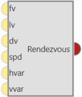
Rendezvous
Rendezvous guidance is used to create a meeting point where the 1x air unit will approach a second unit (either another air or base) within a determined offset.
This guidance updates constantly the vehicle attitude in order to track, with the shortest path, the position of the second unit (named as Base hereafter). This guidance works for both static and moving Base.
Rendezvous navigation is ready for taking Internest input to improve the precision from its guidance, being the most suitable kind for Internest integration.
Warning
In order to produce a guidance computation this block has to be connected to the Guidance Computation block.
-
Configuration menu:
All the parameters that define the rendezvous guidance are detailed.

Rendezvous block configuration -
Patch: This is detailed in the common guidance block parameters, described at the beginning of this section in Guidance blocks common configuration.
-
Set height mode: This is detailed in the common guidance block parameters, described at the beginning of this section in Guidance blocks common configuration.
-
Arcade position/speed transition: This is detailed in the common guidance block parameters, described at the beginning of this section in Guidance blocks common configuration.
-
Set speed: This is detailed in the common guidance block parameters, described at the beginning of this section in Guidance blocks common configuration.
-
Guidance control: This is detailed in the common guidance block parameters, described at the beginning of this section in Guidance blocks common configuration.
-
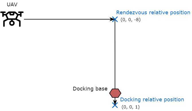
Relative position: For both Docking and Rendezvous the axes are set according to Autopilot 1x orientation (for more information about 1x orientation visit Orientation - Hardware Installation section of the 1x Hardware Manual).
-
Rendezvous relative position: 3D point used to configure the meeting point for the 1x air unit. This point will be tracked by the vehicle and, once reached, it will start travelling to Docking relative position. For VTOL, X and Y components must be equal.
-
Docking relative position: 3D point used to configure the offset for the approaching vehicle to the Docking base. This will be the difference from GNSS position that defines the landing point.
Warning
Usually, the docking relative position is set by slightly overlapping the 'Docking base' in order to ensure that the 1x air unit reaches it, as can be seen in the figure below.
-
-
Base yaw, pitch & roll: Defines the attitude from the Base body. These values affect the navigation by orienting the air unit to be equal to the attitude from the Base unit. To be configured with telemetry (example below).
-
Docking base: Defines the position of the GNSS antenna connected to the Base unit. If the guidance is being configured for a 'moving' Base, a Moving Object must be assigned to it.
- Use Internest: As Rendezvous navigation is prepared to take Internest input, here the user can enable its use and configure a Timeout.
-
The following figure gives an overview of some parameters introduced (note that the negative Z-coordinate is due to the Autopilot 1x axes convention):
In order to know how to configure the Moving Object, which is assigned to Docking Base and the Base attitude, see Data transmission between Veronte Autopilots 1x - Integration examples section of this manual.
Finally, in order to see the Moving Object position in the Veronte Ops interface, in the 1x Air unit:
- Go to Telemetry menu Telemetry panel Data link to VApp.
- Add Moving Object to the list of variables.
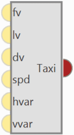
Taxi
Taxi guidance is used to create a linear path along the runway that is followed by the aircraft. This command is normally used in the take-off phase, where the airplane is wanted to keep the direction of the runway while is accelerating until the lift-off point.
Warning
In order to produce a guidance computation this block has to be connected to the Guidance Computation block.
-
Configuration menu:

Taxi block configuration All the parameters that define the taxi guidance are detailed.
-
Patch: This is detailed in the common guidance block parameters, described at the beginning of this section in Guidance blocks common configuration.
-
Set height mode: This is detailed in the common guidance block parameters, described at the beginning of this section in Guidance blocks common configuration.
-
Arcade position/speed transition: This is detailed in the common guidance block parameters, described at the beginning of this section in Guidance blocks common configuration.
-
Set speed: This is detailed in the common guidance block parameters, described at the beginning of this section in Guidance blocks common configuration.
-
Guidance control: This is detailed in the common guidance block parameters, described at the beginning of this section in Guidance blocks common configuration.
-
Runway: Here it is selected a runway previously configured, see the Runway option of Veronte Ops for more information.
Besides, it is possible to use the Advanced mode and select a different end point or direction. By clicking on
or different options will be displayed:

Runway parameters -
End point: Defines the end point of the runway. The two available options are:
-
icon selected: By default, this point is the end of the runway.
But the user can select in the drop-down list any other previously defined point. This includes waypoints defined in the Mission (in Veronte Ops), among many others.
-
icon selected: Alternately, the user can manually define the End point. Then it can be configured in two ways:
- Relative: In this case, the position of the point is relative to another point. That point could be any platform fitted with an Autopilot 1x.
- Absolute: The coordinates can be set in UTM, MGRS, Decimal Degrees or Degress º " '. They are indicated through the latitude, longitude and altitude (being possible to define this last one with respect to the ellipsoid, WGS84, to the sea level, MSL or to the ground, AGL).
-
-
Direction: Defines the runway direction. Again, there are two available options:
-
icon selected: By default, it is the same as the selected runway.
It can be also chosen from a list of options including runway direction, tailwind direction, etc.
-
icon selected: Alternately, it can also be defined as an angle with respect to the magnetic north.
-
-
-
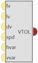
VTOL
VTOL guidance (vertical take-off and landing) is used in multicopters for the take-off and landing operations. This guidance consists on the creation of a vertical line that starts at the point where the platform enters in this guidance.
VTOL guidance generates a vertical straight trajectory.
Warning
In order to produce a guidance computation this block has to be connected to the Guidance Computation block.
-
Configuration menu:

VTOL block configuration All the parameters that define the VTOL guidance are detailed.
-
Patch: This is detailed in the common guidance block parameters, described at the beginning of this section in Guidance blocks common configuration.
-
Set height mode: This is detailed in the common guidance block parameters, described at the beginning of this section in Guidance blocks common configuration.
-
Arcade position/speed transition: This is detailed in the common guidance block parameters, described at the beginning of this section in Guidance blocks common configuration.
-
Set speed: This is detailed in the common guidance block parameters, described at the beginning of this section in Guidance blocks common configuration.
-
Guidance control: This is detailed in the common guidance block parameters, described at the beginning of this section in Guidance blocks common configuration.
-
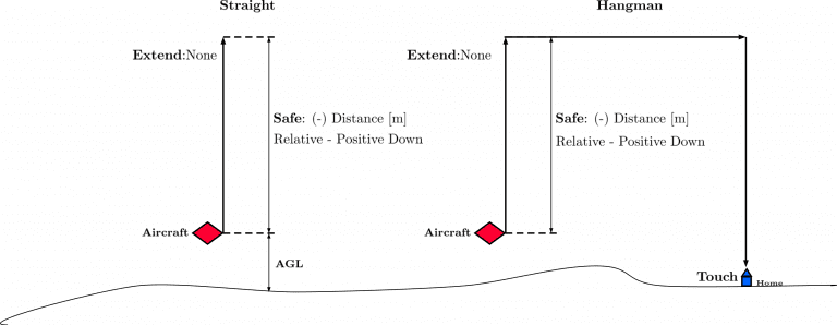
Type: These parameters are used to indicate how the multicopter follows the route during the take-off and landing.
-
The path Straight consists on a vertical line from the point where the vehicle enters in this phase. In the case of a take-off, the line goes from the ground to an altitude indicated by the user.
-
The second option, Hangman, the path consists on a vertical and horizontal line.
-
Extend: When Up or Down are selected, the value set in Safe will be discard, and the platform will ascend or descend, until a next change.
-
Safe: This parameter defines the altitude the aircraft reach. The user can select an Operation Guidance point from the drap-down list (
icon selected) or manually enter a value ( icon selected), this latter value can be:- Relative: Starting from the initial point of the route (current platform position).
-
Absolute altitude: MSL, AGL or WGS84.
As an example, in a Take-Off operation, an altitude of -10000 meters can be indicated as the final point of the route, so it is sure that the multicopter will keep climbing until another phase is commended (via automation or manually).
The same procedure is done in the landing, indicating a big relative distance (for example 100 meters from the starting point), so it is sure that the vehicle reaches the ground, and an automation is set to stop the platform when it touches the surface.
Note
When the option relative is selected, a positive value will made the aircraft descend. Therefore, this value is Positive down.
-
Touch: Additional parameter to be configured when the type Hangman is selected. It defines a point that the aircraft has to reach. For instance, after go Up/Down the set value, the aircraft will perform an horizontal movement according to the defined point. Finally, when the aircrafts is over the point, it will descend until reaches that point.
Usually, this option is used to land at the same point where it took-off (Return to Take-Off point) or when there are obstacles in the area and by performing this movement the platform can avoid them and land safely.
There are 2 ways to configure it:
-
icon selected: By default, this point is the touch point of the runway.
But the user can select in the drop-down list any other previously defined point. This includes waypoints defined in the Mission (in Veronte Ops), among many others.
-
icon selected: Alternately, the user can manually define this point. Then it can be configured in two ways:
- Relative: In this case, the position of the point is relative to another point. That point could be any platform fitted with an Autopilot 1x.
- Absolute: The coordinates can be set in UTM, MGRS, Decimal Degrees or Degress º " '. They are indicated through the latitude and longitude.

Touch options -
-
-
The following image gives an overview of some parameters introduced:
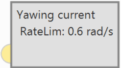
Yawing current
Yaw guidance is used in multicopters to indicate the behavior of the platform in the yaw axis. This option is normally used during the cruise phase of the multicopters, because the route can be carried out with the aircraft without rotating in the yaw axis, or rotate it to point its longitudinal axis parelel to the path.
Yawing current block produces the desired yaw by keeping the yaw reading in on focus. That is, the multicopter will keep the yaw angle it has when entering in the phase that contains this guidance. Desired Yaw = Current Yaw.
-
Input
(Optional) Commanded yaw offset with respect to reference: It is the desired yaw increment with respect to the yaw reference set in the block. -
Configuration menu:

Yaw current block configuration - Limit enabled: When activated, the yaw rate limit will be set to a constant value indicated below.
- Limit rate value: The user can enter this value in different units. The available units are: rad/s, rad/m, rad/h, rps, rpm, rph and °/s.
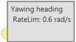
Yawing heading
Yaw guidance is used in multicopters to indicate the behavior of the platform in the yaw axis. This option is normally used during the cruise phase of the multicopters, because the route can be carried out with the aircraft without rotating in the yaw axis, or rotate it to point its longitudinal axis parelel to the path.
Yawing heading block produces the desired yaw as an angle offset from heading.
Heading represents the direction of the velocity vector and, when it is very small, its estimation is more complex and the direction is constantly changing. Because of this, the approximation Yaw = Heading is introduced when the estimated velocity is close to 0.
-
Input
(Optional) Commanded yaw offset with respect to reference: It is the desired yaw increment with respect to the yaw reference set in the block. -
Configuration menu:

Yaw heading block configuration - Limit enabled: When activated, the yaw rate limit will be set to a constant value indicated below.
- Limit rate value: The user can enter this value in different units. The available units are: rad/s, rad/m, rad/h, rps, rpm, rph and °/s.
Yawing north
Yaw guidance is used in multicopters to indicate the behavior of the platform in the yaw axis. This option is normally used during the cruise phase of the multicopters, because the route can be carried out with the aircraft without rotating in the yaw axis, or rotate it to point its longitudinal axis parelel to the path.
Yawing north block produces the desired yaw as an angle offset from north. That is, the yaw of the multicopter will be rotated so that its longitudinal axis always has north as a reference.
-
Input
(Optional) Commanded yaw offset with respect to reference: It is the desired yaw increment with respect to the yaw reference set in the block. -
Configuration menu:

Yaw north block configuration - Limit enabled: When activated, the yaw rate limit will be set to a constant value indicated below.
- Limit rate value: The user can enter this value in different units. The available units are: rad/s, rad/m, rad/h, rps, rpm, rph and °/s.
On the other hand, there are 3 more blocks that help the navigation guidance.
Navigation guidance blocks
These blocks, based on the position of a target, calculate the acceleration required to reach that position.
-
PNav: Proportional navigation block. The algorithm implemented in this block is based on the fact that two vehicles are on a collision course when their direct line-of-sight does not change direction as the range closes. So, PNav dictates that the missile velocity vector should rotate at a rate proportional to the rotation rate of the line of sight (LOS-rate), and in the same direction.

PNav algorithm: A missile (blue) intercepts a target (red) by maintaining constant bearing to it (green) -
Modified PNav: Modified proportional navigation guidance (Old Miura).
- GENEX: Generalized Vector Explicit Guidance (GENEX) block.
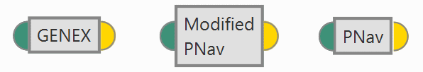
They are configured the same, but with slightly different algorithms:
-
Input
 Pin 0: Target position.
 -
Output
Pin 0: Desired acceleration in body axis. -
Configuration menu:

PNav block configuration The following parameters are configurable:
- Acc limit: The user can fix a limit for the acceleration. The units available for this value are: m/s², ft/s², in/s² and g.
- n: It is a proportional parameter.
© 2025 Embention. All rights reserved.