Signals blocks
Signal blocks include functions for processing and filter signals, control inputs and outputs, etc.
3D Table Interpolation
3D Table Interpolation block returns the value obtained interpolating the configured table with the input variables.
3D Table Interpolation block
Inputs
 Pin 0: X component, columns. Pin 1: Y component, rows.
Output
Pin 0: Value interpolated from table for the input X and Y components.Configuration menu:
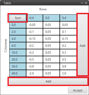
3D Table Interpolation block configuration
Sort: By pressing this button, rows and columns are sorted from lowest to highest.
Add: A row/column is added
Note
If out of range, the value for the closest limit shall be taken.
Acceleration limiter
Acceleration limiter block is a signal first and second derivative limiter.
It is like the Rate limiter block but “improved”, as a less aggressive response is obtained, approaching the desired input in a “softer” way.
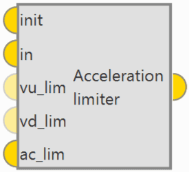
Acceleration limiter block
Inputs
init: Initialization value, this is the output of the block in the first step after on_focus. in: Input signal. (Optional) vu_lim: First derivative limit in the up direction. The value is read as absolute value, this means that the sign of this input is neglected. (Optional) vd_lim: First derivative limit in the down direction. The value is read as absolute value, this means that the sign of this input is neglected. ac_lim: Second derivative limit. The value is read as absolute value, this means that the sign of this input is neglected.Output
Pin 0: Limited signal.
Bound
Bound block limits the input signal and produces a bit to indicate if it was within the allowed range.
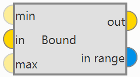
Bound block
Inputs
(Optional) min: Minimum value allowed for input signal. If not defined, it is assumed to be infinity. in: Input signal. (Optional) max: Maximum allowed value for input signal. If not defined, it is assumed to be infinity.Outputs
out: Limited signal. in range: Bit that is true when the input signal is within the allowed range and false otherwise.
User can use the Bound block to monitor critical system parameters that are within operating limits, e.g. airspeed. If not OK, in range can be used to trigger an alarm.
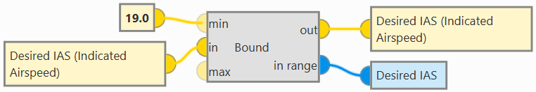
Bound block - Example of use
Derivative
Derivative block is a numerical derivative of an input signal.
Note
As the result of a numerical derivative can be noisy, this block includes a simple first order filter with configurable time constant tau to smooth the output.
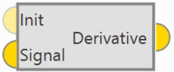
Derivative block
Inputs
(Optional) Init: Optional initial value of the derivative, if not connected a value of zero is assumed. Signal: Signal to compute the numerical derivative.Output
Pin 0: Derived signal.Configuration menu:
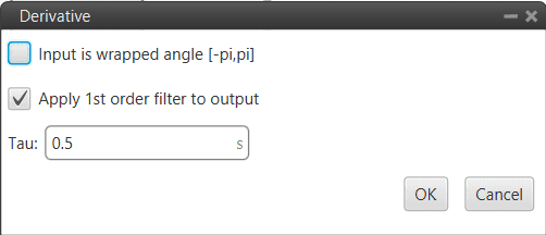
Derivative block configuration
Input is wrapped angle [-pi,pi]: Perform a [-pi, pi] wrap. It should be enabled when using angles.
Apply 1st order filter to output: If enabled, a simple first order filter is applied to smooth the output. By default it is enabled and is also recommended.
Tau: The time constant Tau must be entered.
EWMA Tau filter
EWMA (Exponentially Weighted Moving Average) Tau filter block is a simple first order filter with configurable time constant Tau.
This filter follows the following equation:
Where:
\(\alpha = \frac{dt}{dt + \tau}\)
\(dt\): GNC Timestamp
\(\tau\): Time constant
\(u\): Input value to be filtered
\(y_{-1}\): Initialization value at the first execution of the block (t=0)
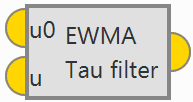
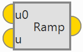
EWMA Tau filter block
Inputs
u0: Initialization value (set in on_focus). u: Current value to filter.Output
Pin 0: Filtered value.Configuration menu:
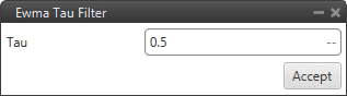
EWMA Tau filter block configuration
Tau: The time constant Tau must be entered.
FFT
Error
The FFT block is temporarily disabled in this version.
FFT (Fast Fourier Transform) block outputs the Fast Fourier Transform of the input signal.
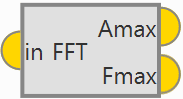
FFT block
Input
in: Input signal.Outputs
Amax: 3D vector containing the magnitude of the three dominant frequencies (sorted from higher to lower magnitude). Fmax: 3D vector containing the frequency of the three dominant frequencies (sorted from higher to lower magnitude).Configuration menu:
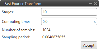
FFT block configuration
Stages.
Computing time.
Hysteresis
Hysteresis block applies hysteresis to input signal to prevent changes in output signal when the input is close to zero.
Hysteresis block
The behavior is as shown in the following diagram:
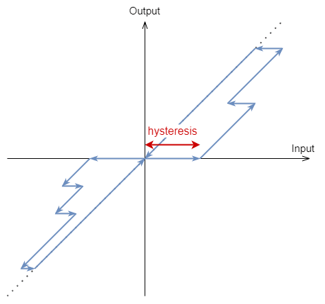
Hysteresis diagram
Input
Pin 0: Input signal.Output
Pin 0: Output signal.Configuration menu:
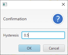
Hysteresis block configuration
Hysteresis: Users must enter the magnitud of the hysteresis.
IIR Filter
IIR Filter block allows the user to define an Infinite Input Response filter, it applies a Z-transform.
IIR Filter block
Input
Pin 0: Input signal.Output
Pin 0: Output signal.Configuration menu:
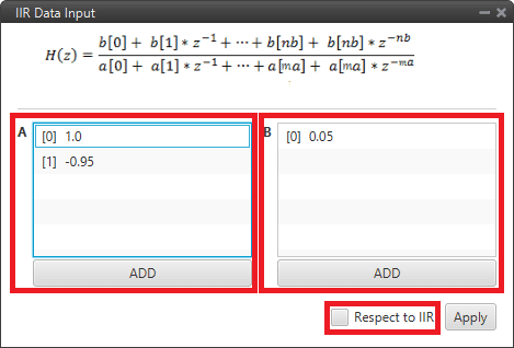
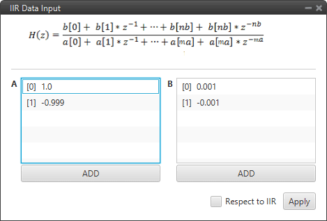
IIR Filter block configuration
A: Filter a coefficients. The user can add as many coefficients a as desired.
B: Filter b coefficients. The user can add as many coefficients b as desired.
Respect to IIR: If enabled, the first time the block is executed, it takes the value of input as the initial offset.
This block can be used as a derivative if configured as shown in the following figure:
IIR Filter block - Derivative example
Integrator
Integrator block is a numerical integrator. It calculates the numerical integral of the input signal using the trapezoidal formula.
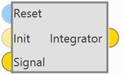
Integrator block
Inputs
(Optional) Reset: Optional reset, assumed false if not connected. (Optional) Init: Optional initial value of the integral, if not connected a value of zero is assumed. Signal: Signal to integrate.Output
Pin 0: Integrated signal.
Interpolation Vector
Interpolation Vector block applies the configured table interpolation over each of the components of the input vector.
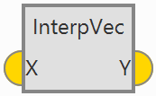
Interp Vec block
Input
X: Input vector.Output
Y: Interpolated output vector.Configuration menu:
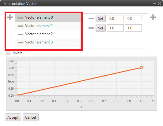
Interp Vec block configuration
 : Users should add as many Vector elements as there are components in the input vector.
Points: The interpolation function of each component must be configured by the user. It is represented by the graph below.
Invert: If enabled, the y axis of the function will correspond to the input vector and the x axis to the interpolated output vector.
Ramp
Ramp block will ramp up to the final value defined as input, starting from the initial value defined as input, and respecting the parameters Ramp Delay and Ramp Time.
Ramp block
Inputs
u0: Initial value of the ramp, read only in on_focus. u: Final value of the ramp, updated in each step.Output
Pin 0: Output ramp value.Configuration menu:
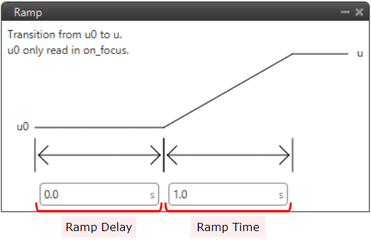
Ramp block configuration
Ramp Delay: Time before starting the ramp.
Ramp Time: Time in which the variable must change from the initial value to the final value.
Rate limiter
Rate limiter block limits the rate of change of the input signal. It returns the signal input, but limiting its maximum rate of change.
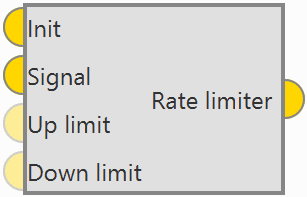
Rate limiter block
If the rate of change of the input is higher than the maximum, the output will try to converge to the input, but respecting the imposed maximum rate of change.
The first time the block is executed the output will be equal to Init.
Inputs
Init: Initialization value, this is the output of the block in the first step after on_focus. Signal: Input signal. (Optional) Up limit: Rate limit in the up direction. The value is read as absolute value, this means that the sign of this input is neglected. (Optional) Down limit: Rate limit in the down direction. The value is read as absolute value, this means that the sign of this input is neglected.Output
Pin 0: Rate-limited signal.Configuration menu:
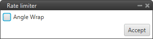
Rate limiter block configuration
Angle wrap: Perform a [-pi, pi] wrap. It should be enabled when using angles.
This block can be used to avoid instantaneous spikes and spikes in control signals, effectively reducing control noise and smoothing flight:
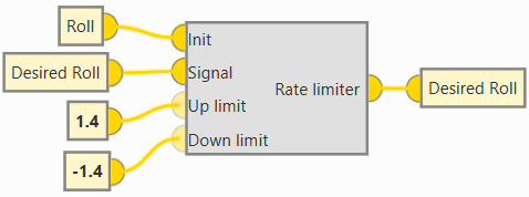
Rate limiter block - Example of use
Signal generator
Signal generator block is a wave signal generator.
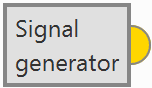
Signal generator block
Output
Pin 0: Signal generated according to the configured type.Configuration menu:
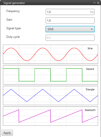
Signal generator block configuration
Frequency: Frequency of the signal.
Gain: Gain of the signal
Signal type: Users must select the type of signal to be generated. The available options are: Sine, Square, Triangular and Sawtooth.
Note
An example of the square signal type is shown below.
Duty cycle: Duty cycle of the signal. Can only be modified when Square signal is selected.
An example is given below:
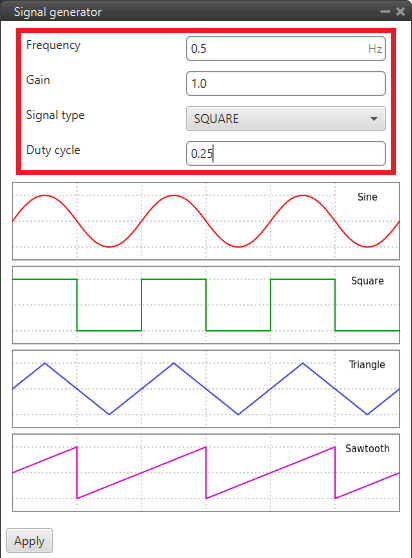
Signal generator block - Configuration example
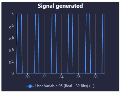
Signal generator block - Example of signal generated